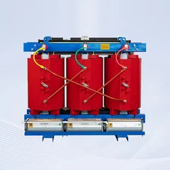
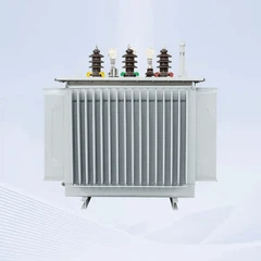


10KV 35KV Oil-Immersed Transformer
Have questions? GNEE sales representatives are available for live chat now
Send E-mail: sales@gneeelectric.com
Tel: +8615824687445
Henan GNEE Electric Co., Ltd. is one of the most reliable manufacturers and suppliers of 10kv 35kv oil-immersed transformer in China. If you're going to buy customized 10kv 35kv oil-immersed transformer made in China, welcome to get quotation from our factory. Quality products and reasonable price are available.
10KV Oil-immersed Transformer
Phase: Three
Service Voltage: 6KV~10KV
Rated Capacity:30KVA~2500kVA
Vector group:Yyn0, Dyn11
Cooling type: ONAN
Core material: Silicon Steel
Winding material: Copper/aluminum
Available fluids: mineral oil and ester fluids
Purpose:Three-phase oil transformers of a sealed version, without oil conservators
are intended for transforming of electric energy in networks of power systems and in energy consumer network.

- Low loss: low no-load loss,low load loss, low operating costs.
- Powerful anti-short circuit capacity, high anti-lightning impulse capacity.
- Long service life: The oil tank adopts a fully sealed structure, the tank and the box edge can be connected by bolts, which can be isolated from the external environment to prolong the service life of the transformer.
- High reliability: The seal parts of the oil tank have been improved to increase the reliability.

10KV Oil-Immersed Transformer Parameters
| 10KV Oil-Immersed Distribution Transformer Parameters | ||||||||||||
| Rated Power (KVA) |
High Voltage (KV) |
Low Voltage (KV) |
Vector group |
Class I | Class II | ClassIII | No-load Current (%) |
Short Circuit Impedance (%) |
||||
| No-load Loss (W) |
On-load Loss (W) |
No-load Loss (W) |
On-load Loss (W) |
No-load Loss (W) |
On-load Loss (W) |
|||||||
| 30 | 66.3 10 10.5 11 | 0.4 | YynO Dyn11 |
65 | 455/430 | 70 | 505/480 | 80 | 630/600 | 2.1 | 4.0 | |
| 50 | 80 | 655/625 | 90 | 730/695 | 100 | 910/870 | 2.0 | |||||
| 63 | 90 | 785/745 | 100 | 870/830 | 110 | 1090/1040 | 1.9 | |||||
| 80 | 105 | 945/900 | 115 | 1050/1000 | 130 | 1310/1250 | 1.8 | |||||
| 100 | 120 | 1140/1080 | 135 | 1265/1200 | 150 | 1580/1500 | 1.6 | |||||
| 125 | 135 | 1360/1295 | 150 | 1510/1440 | 170 | 1890/1800 | 1.5 | |||||
| 160 | 160 | 1665/1585 | 180 | 1850/1760 | 200 | 2310/2200 | 1.4 | |||||
| 200 | 190 | 1970/1870 | 215 | 2185/2080 | 240 | 2730/2600 | 1.3 | |||||
| 250 | 230 | 2300/2195 | 260 | 2560/2440 | 290 | 3200/3050 | 1.2 | |||||
| 315 | 270 | 2760/2630 | 305 | 3065/2920 | 340 | 3830/3650 | 1.0 | |||||
| 400 | 330 | 3250/3095 | 370 | 3615/3440 | 410 | 4520/4300 | 1.0 | |||||
| 500 | 385 | 3900/3710 | 430 | 4330/4120 | 480 | 5410/5150 | 1.0 | |||||
| 630 | 460 | 4460 | 510 | 4960 | 570 | 6200 | 0.9 | 4.5 | ||||
| 800 | 560 | 5400 | 630 | 6000 | 700 | 75 00 | 0.8 | |||||
| 1000 | 665 | 7451 | 745 | 8240 | 830 | 10300 | 0.7 | |||||
| 1250 | 780 | 8640 | 870 | 9600 | 970 | 12 DOO | 0.6 | |||||
| 1600 | 940 | 10440 | 1050 | 11600 | 1170 | 14500 | 0.6 | |||||
| 2000 | 1085 | 13180 | 1225 | 14640 | 1360 | 18 | 3 DO | 0.4 | 5 | |||
| 2500 | 1280 | 13360 | 1440 | 14840 | 1600 | 21200 | 0.32 | |||||
35KV Oil-Immersed Transformer

- The full inclined step joint is adopted to improve the flux direction, eliminate the local flux saturation phenomenon at the joint of the iron core, reduce the no-load loss and no-load current of the iron core, and reduce the transformer noise.
- In order to enhance the ability to resist short circuit, a number of pressure nails are distributed around the pressboard, and the upper and lower high and low pressure clips are connected by support beams, so that the iron core becomes a whole.
- The surface of the core column is coated with silicon steel sheet special end-gluing, so that the silicon steel cut and cut are bonded together, and the iron core becomes z whole body after curing.
- High strength electrical laminated wood supports are used between the lower part of the body and the wall of the tank, making the lower part safe and reliable positioning.

35KV Oil-Immersed Transformer Parameters
| 35KV Oil-Immersed Distribution Transformer Parameters | |||||||||
| Rated Power(KVA) | Vector group |
Class I | Class II | ClassIII | Short Circuit Impedance (%) |
||||
|
No-load Loss (KW) |
On-load Loss (75℃ KW) |
No-load Loss (KW) |
On-load Loss (75℃ KW) |
No-load Loss (KW) |
On-load Loss (75℃ KW) |
||||
| 3150 | YNd11 | 1.7 | 20.7 | 2.0 | 20.7 | 2.4 | 21.9 | 7 | |
| 4000 | 2.0 | 24.6 | 2.3 | 24.6 | 2.9 | 25.9 | |||
| 5000 | 2.4 | 28.2 | 2.8 | 28.2 | 3.5 | 29.7 | |||
| 6300 | 2.9 | 31.5 | 3.4 | 31.5 | 4.2 | 33.3 | |||
| 8000 | 4.0 | 34.6 | 4.7 | 34.6 | 5.8 | 36.5 | |||
| 10000 | 4.8 | 40.8 | 5.7 | 40.8 | 7.0 | 43.0 | 8 | ||
| 12500 | 5.5 | 48.4 | 6.5 | 48.4 | 8.0 | 51.1 | |||
| 16000 | 6.7 | 59.2 | 7.9 | 59.2 | 9.7 | 62.5 | |||
| 20000 | 7.9 | 71.6 | 9.4 | 71.6 | 11.5 | 75.5 | |||
| 25000 | 9.4 | 84.6 | 11.1 | 84.6 | 13.6 | 89.3 | 10 | ||
| 31500 | 11.1 | 100.8 | 13.1 | 100.8 | 16.2 | 106.4 | |||
Single Phase Pole Mounted Oil Type Distribution Transformer
- Oil-filled single-phase overhead transformers designed and produced normally used for stepping utility distribution voltages(ranging from 2400 to 34500 volts) down to lower utilization voltages.
- Although some are used for stepping down to commercial and industrial voltages such as 277, 240/480, 2400 and 4800,most are used for stepping down to the single-phase voltage of 120/240.
- These same transformers are also used for small substations,miscellaneous applications and can serve to step up voltages.

Oil-filled single-phase overhead transformer Parameters
| 10kva-500kva Single-phase oil immersed transformer | ||||||
| Rated Cap acity(kVA) | High | Low Voltage(v) | Connection Symbol | Standard | Short-circuit impedance(%) | Efficiency |
| Voltage(v) | (%) | |||||
| 10 | 4160 7200 12000 12470 13200 13800 19920 24940 34500 |
110 220 230 400 480 |
II0,II6 | IEEE/ANSI/ DOE | 1.8-4% | 98.7 |
| 15 | 98.82 | |||||
| 25 | 98.95 | |||||
| 37.5 | 99.05 | |||||
| 50 | 99.11 | |||||
| 75 | 99.19 | |||||
| 100 | 99.25 | |||||
| 167 | 99.33 | |||||
| 250 | 99.39 | |||||
| 333 | 99.43 | |||||
| 500 | 99.49 | |||||

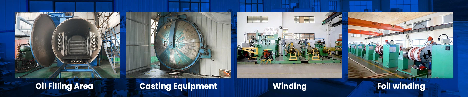
Process Technology:
Core:
- Our transformer's core is made of high quality cold rolled grain oriented silicon steel sheet with high magnetic permeability. It is using full 45° slope lamination, so that the noload loss and the no-load current are reduced efficiently.
LV Winding:
- LV windings are adopting superior foil conductors or made of 100% copper wire, thus to obtain better amperturn balance and reduce more transverse magnetic flux leakage. Then to greatly improves transformer's anti-short circuit capability.
- Excellent design of oil passage structure, greatly increasing the coils' heat dispersion effect. It helps to decrease temperature rise of the LV winding and improve transformers' overload capability.
HV Winding
- HV windings are made of superior copperconductor wires. Adopting fiberglass to reinforced insulation.
- HV windings are adopted optimized structure to improve transformer's distribution of electric field.
- We use our existing technology calculate and analysis Lightning wave process simulation. Then substantially improving product's antilighting capability.
Insulation construction:
- Aclass level Insulation construction. The high-voltage coil and low-voltage coil are placed with the same center. Between the coils, use the thin paper cylinder with little oil clearance construction.
Tank:
- The tank is jointed with highquality steel. The surface is eliminated rust phosphate coating and painted with the type of FVC anticorrosive paint. It has ability to prevent the corrosion from oil and chemical matter. It can be broadly applied to outdoors with bad environment for its contour artistic, easily installation and maintenance free.
Components:
- All the power transformers equipped with highvoltage bushing, low-voltage bushing, oil-relesase valve earthling boilt, lifting board, name plate, pressure vale and so on. The transformers which are over 800kVA are equipped with signal thermometer and gas relay.
Hot Tags: 10kv 35kv oil-immersed transformer, China 10kv 35kv oil-immersed transformer manufacturers, suppliers, factory, transformer environmental protection, Oil Immersed Transformers, Single Phase Oil Filled Transformers, transformer power rating standard, transformer international standard, transformer protection standard
You Might Also Like


Send Inquiry