


How does a large power transformer transfer energy?
Oct 10, 2025
Leave a message
As a leading supplier of large power transformers, I am often asked about how these remarkable pieces of equipment transfer energy. In this blog post, I will delve into the science behind the energy transfer process in large power transformers, highlighting the key principles and components involved. Additionally, I will introduce some of our top - of - the - line products, providing links for those interested in learning more.
The Basics of Power Transformers
A large power transformer is an electrical device that transfers electrical energy between two or more circuits through electromagnetic induction. It is a crucial component in the power grid, used for stepping up or stepping down voltage levels to facilitate efficient power transmission and distribution.
The fundamental principle of a power transformer is based on Faraday's law of electromagnetic induction. This law states that a change in the magnetic field within a closed loop of wire induces an electromotive force (EMF) or voltage in the wire. In a transformer, this is achieved by using two coils of wire, known as the primary and secondary coils, wound around a common iron core.
Components of a Large Power Transformer
Iron Core
The iron core serves as a magnetic path for the magnetic flux generated by the primary coil. It is typically made of laminated sheets of high - permeability magnetic material, such as silicon steel. The lamination helps to reduce eddy current losses, which are caused by the induction of circulating currents within the core. The core is designed to have a low reluctance, allowing the magnetic flux to flow easily between the primary and secondary coils.
Primary and Secondary Coils
The primary coil is connected to the input voltage source, while the secondary coil is connected to the load. The number of turns in each coil determines the voltage transformation ratio of the transformer. If the number of turns in the secondary coil is greater than the number of turns in the primary coil, the transformer is a step - up transformer, which increases the voltage. Conversely, if the number of turns in the secondary coil is less than the number of turns in the primary coil, it is a step - down transformer, which decreases the voltage.
Insulation
Insulation is a critical component in a large power transformer. It prevents electrical short - circuits between the coils and the core, as well as between different parts of the coils themselves. High - quality insulation materials, such as paper, oil, and synthetic polymers, are used to ensure the safe and reliable operation of the transformer. The insulation must be able to withstand high voltages and temperature variations without breaking down.
Cooling System
Large power transformers generate a significant amount of heat during operation due to the losses in the core and coils. A cooling system is required to dissipate this heat and maintain the transformer at a safe operating temperature. Common cooling methods include oil - immersed cooling, where the transformer is filled with insulating oil that circulates through radiators to transfer heat to the surrounding air, and forced - air cooling, which uses fans to blow air over the radiators.
Energy Transfer Process
When an alternating current (AC) is applied to the primary coil, it creates a changing magnetic field around the coil. This magnetic field passes through the iron core and links with the secondary coil. According to Faraday's law, the changing magnetic field induces an EMF in the secondary coil.
The induced EMF in the secondary coil is proportional to the rate of change of the magnetic flux and the number of turns in the secondary coil. The relationship between the primary and secondary voltages is given by the following formula:
[ \frac{V_s}{V_p}=\frac{N_s}{N_p} ]
where (V_s) is the secondary voltage, (V_p) is the primary voltage, (N_s) is the number of turns in the secondary coil, and (N_p) is the number of turns in the primary coil.
The power transferred from the primary to the secondary coil is approximately equal, neglecting losses. So, if the voltage is stepped up in the secondary coil, the current is stepped down proportionally, and vice versa. This is based on the principle of conservation of energy, which states that power (P = VI) remains constant in an ideal transformer.


In a real - world scenario, there are some losses in a power transformer. These losses include copper losses, which are due to the resistance of the coils, and core losses, which are composed of hysteresis losses and eddy current losses. Copper losses can be reduced by using thicker wire for the coils, while core losses can be minimized by using high - quality core materials and proper lamination.
Our Product Offerings
As a supplier of large power transformers, we offer a wide range of products to meet the diverse needs of our customers. Here are some of our featured products:
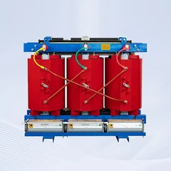
- S(B)H15 - M Series Sealed Amorphous Alloy Power Transformer: This series of transformers uses amorphous alloy cores, which have lower core losses compared to traditional silicon steel cores. They are suitable for applications where energy efficiency is a top priority.
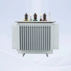
- 110kV three - phase oil filled power transformer: Designed for high - voltage power transmission and distribution, this transformer offers reliable performance and excellent insulation properties. It is equipped with a robust cooling system to ensure stable operation under heavy loads.
- Manufactures 100kVA 3 Phase Oil Immersed Type Power Transformer: This transformer is a popular choice for small to medium - sized power distribution networks. It provides efficient power transfer and is easy to install and maintain.
Conclusion
Understanding how a large power transformer transfers energy is essential for anyone involved in the power industry. By leveraging the principles of electromagnetic induction and carefully designing the components, we can ensure the efficient and reliable transfer of electrical energy.
If you are interested in our large power transformers or have any questions about energy transfer in transformers, we encourage you to contact us for procurement and further discussion. Our team of experts is ready to assist you in finding the right solution for your specific needs.
References
- Grover, F. W. (1946). Inductance Calculations: Working Formulas and Tables. Dover Publications.
- Alexander, C. K., & Sadiku, M. N. O. (2009). Fundamentals of Electric Circuits. McGraw - Hill.
- Westinghouse Electric Corporation. (1964). Electrical Transmission and Distribution Reference Book. Westinghouse Electric Corporation.
Send Inquiry