


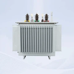







11 kV Fully Sealed Three-Phase Oil-Immersed Distribution Transformer: S11 and S13 Data
Nov 11, 2025
Leave a message
The 11 kV Distribution Class in Practice
11 kV is the most widely used medium-voltage distribution level in many networks outside Europe: it feeds rural lines, industrial plants, commercial complexes, water pumping stations and renewable energy collectors, and it is stepped down to 0.4 kV or 0.415 kV at the point of use. The fully sealed three-phase oil-immersed transformer is the standard solution for that duty because it combines a low impedance, high short-circuit withstand and a maintenance-light tank with a cost per kVA that dry-type units cannot match at this capacity range.
Series coverage runs from 25 kVA or 30 kVA up to 2500 kVA, with higher ratings available on request. Both 50 Hz and 60 Hz designs are produced, and primary voltages can be set at 6, 6.3, 6.6, 10, 10.5 or 11 kV.
Efficiency Series and Loss Comparison
| Capacity (kVA) | S11 no-load loss (W) | S11 load loss (W) | S13 no-load loss (W) | S13 load loss (W) |
|---|---|---|---|---|
| 30 | 100 | 630 | 80 | 630 |
| 100 | 200 | 1580 | 150 | 1580 |
| 250 | 400 | 3200 | 290 | 3200 |
| 630 | 810 | 6200 | 570 | 6200 |
| 1000 | 1150 | 10300 | 830 | 10300 |
| 1600 | 1640 | 14500 | 1170 | 14500 |
| 2500 | 2290 | 21200 | 1830 | 21200 |
Moving from the S11 family to the S13 family reduces no-load loss, which is the component that runs continuously from the moment the transformer is energised. For a distribution transformer on a lightly loaded rural feeder, no-load loss dominates the annual energy bill, so the higher-grade core usually pays back even though the first cost is higher.
Windings, Core, Tank and Accessories
Windings are copper, paper insulated, arranged as concentric coils on a laminated core built from 0.35 mm surface-insulated grain-oriented silicon steel, a material class covered by specifications such as ASTM A876. The complete active part is vacuum dried to remove moisture from the paper insulation before the tank is filled. The sealed corrugated tank absorbs oil expansion and isolates the oil from the atmosphere, so oxidation, moisture ingress and sludge formation are kept low over a long service life. Standard accessories include an oil-level indication, a filling and drain arrangement, an earthing terminal, a rating plate and a cable box; a Buchholz relay or pressure relief device is fitted where the protection scheme calls for it.
Impedance, Temperature Rise and Noise
Impedance voltage is 4 % up to 630 kVA and 4.5 % above that in the standard series, which keeps fault current and voltage regulation within normal distribution practice. Temperature rise follows IEC 60076-2, with a top-oil limit of 60 K and an average winding limit of 65 K for ONAN cooling with mineral oil, so the corrugated wall must be sized not only for the total loss but for the load cycle the unit will actually see. Vector groups Dyn11, Yyn0 and Yzn11 are produced; the choice sets the phase displacement between primary and secondary and therefore how the network protection and the load are connected.
Dimension and Weight Reference
| Capacity (kVA) | Reference L x W x H (mm) | Total weight (kg) |
|---|---|---|
| 100 | 790 x 700 x 1040 | 520 |
| 250 | 1200 x 800 x 1190 | 955 |
| 630 | 1500 x 970 x 1360 | 1850 |
| 1000 | 1690 x 1190 x 1530 | 2570 |
| 1600 | 1800 x 1250 x 1660 | 3520 |
Dimensions and masses are reference values for the standard sealed design and shift with the vector group, the tapping range, the cable box arrangement and the required impedance, so they are confirmed against the final drawing before foundations and cable boxes are set.
Testing and Standards
Each unit receives routine tests in accordance with IEC 60076-1: winding resistance, ratio and vector group check, impedance voltage and load loss, no-load loss and current, plus dielectric tests on the insulation. Temperature rise and lightning impulse are type tests on the design. Insulation levels for the 12 kV class are defined in IEC 60076-3. Oil conforms to IEC 60296 and its breakdown voltage to IEC 60156. Chinese national equivalents are the GB 1094 series, with loss grades referenced to GB 20052-2020.
Frequently Asked Questions
Q: Why choose a fully sealed transformer for an 11 kV network?
A: The sealed corrugated tank isolates the oil from air, so moisture ingress and oxidation are minimised and no oil change is needed in normal service, which reduces maintenance for units installed on remote feeders.
Q: What is the difference between the S11 and S13 series?
A: The main difference is no-load loss. At 1000 kVA the S11 design shows 1150 W no-load loss against 830 W for the S13 design, while load loss stays at 10300 W in both cases.
Q: Which vector group should be specified?
A: Dyn11 is the standard choice for a distribution step-down unit; Yyn0 and Yzn11 are available where the network, the load balance or the protection scheme requires those connections.
Q: Can a 60 Hz unit be supplied to the same drawings as a 50 Hz unit?
A: No. Core flux density and loss behave differently at the two frequencies, so the core, the loss figures and the temperature rise are designed for the stated frequency. Both 50 Hz and 60 Hz designs are produced.
Q: How is the correct capacity selected?
A: From the connected load converted to kVA at the expected power factor, plus allowance for future growth and for motor starting. Impedance voltage of 4 % or 4.5 % then keeps fault level and voltage drop inside the design limits of the downstream switchgear.
Send Inquiry