


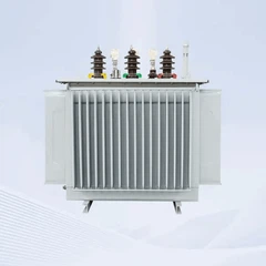
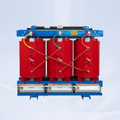







11kv transformer
Nov 05, 2025
Leave a message
What is the 11 kV power line?
11kV transformers are typically used for power distribution in residential areas. They step down higher voltage levels to 11,000 volts for delivery to homes and businesses.
An 11 kV power line is a medium-voltage transmission line used for distributing electricity from substations to smaller transformers before reaching end users. It is commonly found in industrial, commercial, and rural power distribution networks, featuring heavy-duty construction for reliable operation in harsh conditions.
Different Types Of 11kv Transformers From HENAN GNEE ELECTRIC CO., LTD.
1.11kv 400KVA Three Phase Pole Mounted Distribution Transformer
This 400 KVA transformer was delivered to Viet Nam. the rated power of the transformer is 400 KVA. the primary voltage of the transformer is 11 KV and secondary voltage is 0.415 KV. Different from dry type transformer, it is a Liquid Dielectric Transformer, using mineral oil as cooling material.
Technical Specification
400 KVA transformer specifications and data sheet
|
Delivered to |
Viet Nam |
|
Model |
S11-400 KVA-11/0.415KV |
|
Type |
Oil Immersed Transformer |
|
Standard |
IEC60076 |
|
Rated Power |
400KVA |
|
Frequency |
50 HZ |
|
Phase |
Three |
|
Cooling Type |
ONAN |
|
Primary Voltage |
11 KV |
|
Secondary Voltage |
0.415 KV |
|
Winding Material |
Copper |
|
Vector Group |
Dyn11 |
|
Impedance |
5% |
|
Tap Changer |
NLTC |
|
Tapping Range |
±2*2.5% |
|
No Load Loss |
0.57W |
|
On Load Loss |
4.3KW |
|
Accessories |
Standard Configuration |
|
Remarks |
N/A |
There are two common types of transformer tank:
1. Barrel type Tank: Generally used for small and medium-sized transformers
2. Bell type tank: for large transformers.
Finished 400 KVA 11/0.4KV Transformer

2.11KV 0.433 Kv 315 Kva Distribution Transformer
HENAN GNEE ELECTRIC CO., LTD. aims to create a 11 0.433 kv 315 kva distribution transformer with high energy efficiency and excellent ability on resistant to sudden short circuit.
Meanwhile, HENAN GNEE ELECTRIC CO., LTD. will keep the competitive advantages not only in the designing, but also maximize use spending to manufacture a 11 0.433 kv 315 kva distribution transformer.
The company strictly follows the requirement of ISO 9001 quality management system to ensure each procedure of producing 11 0.433 kv 315 kva distribution transformer is smooth.
In order to achieve better energy saving effects, HENAN GNEE ELECTRIC CO., LTD. has conducted in depth research and development and innovation on the basis of S13 11 0.433 kv 315 kva distribution transformer. HENAN GNEE ELECTRIC CO., LTD. have adopted new materials, new processes and independent innovative technical means to optimize the design of the transformer core and coil structure. These improvements make the S20 11 0.433 kv 315 kva distribution transformer excellent in reducing no load losses, load losses and noise level.
Specifically, the difference between the S20 11 0.433 kv 315 kva distribution transformer and the S13 11 0.433 kv 315 kva distribution transformer is mainly reflected in energy consumption. The S20 11 0.433 kv 315 kva distribution transformer has 10% lower no-load loss and load loss than the S13 11 0.433 kv 315 kva distribution transformer. Even a S20 11 0.433 kv 315 kva distribution transformer has a higher material costs, it will achieve an outstanding budget on energy consumption.
the 300 kva 11 0.433 kv 315 kva distribution transformer 315 kva Technical Data:
| Rated Capacity: | 315 kVA ; |
| Mode: | S20-M-315 or depends; |
| Primary Voltage: | 11kV; |
| Secondary Voltage: | 0.433kV; |
| No Loading Loss: | 305 W ± 15%; |
| Loading Loss: | 3065 W ± 15%; |
| Vector Group: | Dyn5;Dyn11; Yyn0; |
| Tapping Method: | OFFLCT; |
| Tapping Range: | ± 5.0%; ± 2.5%; |
| Phase Number: | Three Phase. |

|
1. iron core |
Silicon steel sheet with high magnetic conductivity particle orientation: silicon steel sheet with core type. Full inclined joint |
|
2.winding |
The system uses tile oil channel, non-immersion paint process, tightening belt practice tie: windings are concentric line diagram: high voltage windings should be connected to the voltage requirements of the tap. Lead to tap switch, which is mounted on the box cover. After the power supply is cut off, 10kV and 20kV voltage can be transferred, and the tap voltage can be changed. |
|
3.Safety protection device |
30-2000kVA transformer equipped with pressure release reading; Gas relay with alarm and jump terminal can be installed according to the user number; |
|
4.Oil temperature measuring device |
The tube seat of the glass thermometer is installed on the top of the tank and 120+-10mm is stopped in the tank. 1000-2000kVA transformer equipped with outdoor signal thermomet |
3.11kv No-load Voltage Regulation Transformers
| echnical Parameter for S11 Series 6kv-11kv No-load Voltage Regulation Transformers | ||||||||||||
| Rated Capacit Y(KVA |
Voltage Combination | Connection Group Symbol |
No- load Loss (W) |
Toad Loss (W) |
Impedance Voltage(%) |
No-load Current (%) |
L*W*H(mm | Gauge Horizonta 1*Vertica (mm) |
Active parts Weight (kg *Oil Weight (kg) |
Tota Weigh (kg) |
||
| High Voltag e (KV |
Tapping Range of High Voltage |
Low Voltag e (KV) |
||||||||||
| 30 | 6 6.3 10 10.5 11 |
±5% ±2x2.5% |
0.4 | Dyn11 Yzn11 Yyn0 |
100 | 630/600 | 4 | 2.8 | 980*735*1145 | 400*400 | 178*78 | 355 |
| 50 | 130 | 910/870 | 2.5 | 1017*758*1205 | 450*400 | 240*92 | 415 | |||||
| 63 | 150 | 1090/1040 | 2.4 | 1035*785*1285 | 450*400 | 285*105 | 505 | |||||
| 80 | 180 | 1310/1250 | 2.2 | 1065*800*1290 | 450*400 | 330*110 | 540 | |||||
| 100 | 200 | 1580/1500 | 2.1 | 1072*820*1305 | 450*400 | 345*116 | 590 | |||||
| 125 | 240 | 1890/1800 | 2 | 1155*1105*131 | 450*400 | 415*135 | 705 | |||||
| 160 | 280 | 2310/2200 | 1.9 | 1235*850*1535 | 550*550 | 485*135 | 835 | |||||
| 200 | 340 | 2730/2600 | 1.8 | 1282*860*1557 | 550*550 | 582*168 | 965 | |||||
| 250 | 400 | 3200/3050 | 1.7 | 1310*940*1605 | 550*550 | 695*210 | 1135 | |||||
| 315 | 480 | 3830/3650 | 1.6 | 1465*1120*191 | 660*650 | 855*255 | 1520 | |||||
| 400 | 570 | 4520/4300 | 1.5 | 1440*1165*172 | 660*650 | 950*295 | 1590 | |||||
| 500 | 680 | 5410/5150 | 1.4 | 1510*1250*184 | 660*650 | 1150*320 | 1905 | |||||
| 630 | 810 | 6200 | 4.5 | 1.3 | 1650*1140*192 | 660*650 | 1500*435 | 2015 | ||||
| 800 | 980 | 7500 | 1.2 | 2125*1175*231 | 820*820 | 1910*760 | 3510 | |||||
| 1000 | 1150 | 10300 | 1.1 | 2150*1380*257 | 820*820 | 2125*880 | 3850 | |||||
| 1250 | 1360 | 12000 | 1 | 2355*1485*257 | 820*820 | 2605*960 | 4610 | |||||
| 1600 | 1640 | 14500 | 0.9 | 2335*1750*263 | 820*820 | 3125*1150 | 5420 | |||||
| 2000 | 1940 | 18300 | 5 | 0.4 | 1940*1400*170 | 820*820 | 2420*780 | 4200 | ||||
| 2500 | 2290 | 21200 | 0.4 | 2050*1480*180 | 820*820 | 2560*780 | 4680 | |||||
| Note:Parameter is for reference only,if any changes should follow the factory technical data. | ||||||||||||
4.S11 Series 11kv Low-loss And Non-exciting Regulation Power Transformer
|
Technical Data Of S11 Series 10kv Low-loss And Non-exciting Regulation Power Transformer
|
||||||||
|
Rated Capacity(kva)
|
Voltage Combined
|
Vector-group
|
No-load Loss
|
75℃ Load loss
|
No-load current
|
Short-circuit Impedence
|
||
|
HV(kV)
|
Tapping Ranges
|
LV(kV)
|
||||||
|
30
|
6
6.3
10
10.5
11
or others
|
±5%±2×2.5%
|
0.4
or others
|
Dyn11
Yyn0
or others
|
100
|
630/600
|
0.80
|
4.0
|
|
50
|
130
|
910/870
|
0.75
|
|||||
|
63
|
150
|
1090/1040
|
0.75
|
|||||
|
80
|
180
|
1310/1250
|
0.70
|
|||||
|
100
|
200
|
1580/1500
|
0.65
|
|||||
|
125
|
240
|
1890/1800
|
0.65
|
|||||
|
160
|
280
|
2310/2200
|
0.60
|
|||||
|
200
|
340
|
2730/2600
|
0.50
|
|||||
|
250
|
400
|
3200/3050
|
0.50
|
|||||
|
315
|
480
|
3830/3650
|
0.45
|
|||||
|
400
|
570
|
4520/4300
|
0.45
|
|||||
|
500
|
680
|
5410/5150
|
0.40
|
|||||
|
630
|
810
|
6200
|
0.40
|
4.5
|
||||
|
800
|
980
|
7500
|
0.35
|
|||||
|
1000
|
1150
|
10300
|
0.35
|
|||||
|
1250
|
1360
|
12000
|
0.30
|
|||||
|
1600
|
1640
|
145000
|
0.30
|
|||||
Send Inquiry