










How to Calculate Protection Settings for High-Voltage Switchgear?
Nov 09, 2026
Leave a message
1. What Is "Protection" Inside a High-Voltage Switchgear Panel?
Inside every 6kV / 10kV / 35kV switchgear panel, three core components handle "protection":
- Circuit breaker - the actuator that physically interrupts the fault current.
- Current transformer (CT) - steps down hundreds or thousands of amperes to a secondary current of 5 A or 1 A.
- Voltage transformer (PT / VT) - steps down medium voltage (e.g., 10 kV) to a standard 100 V secondary.
And then there is the microprocessor-based protection relay (also called a "numerical relay" or IED) - the real "brain" that makes the decision.
Think of electrical equipment as a human body and faults as diseases:
- Short circuit = a ruptured artery - current surges to thousands of amps and can destroy equipment in seconds. Must be cleared instantly.
- Overload (overcurrent due to excess load) = chronic overeating - current is moderate but heat builds up over time. Alarm first, then trip if sustained.
- Single-phase earth fault = a "leak" - fault current is small, but voltage imbalance and touch voltage become dangerous. Must be detected promptly.

The protection relay is the "doctor + first responder." Protection settings are the diagnostic criteria - "how severe, for how long, before we act." Setting calculation is the process of defining those criteria for every panel and every fault type.
Four fundamental requirements guide all protection design - the "four qualities":
- Selectivity - only the nearest breaker trips; no cascading blackouts.
- Speed (fast operation) - faults are cleared as quickly as possible.
- Sensitivity - real faults are reliably detected even at minimum fault level.
- Dependability & security - operates when it should, never when it shouldn't.
- Setting calculation is all about balancing these four.
Disclaimer: The coefficients in this article represent typical engineering ranges used to explain the principles. Actual settings must be calculated according to current standards (e.g., IEC 60255, IEEE C37, GB/T 14285, DL/T 584, DL/T 1502) and the relay manufacturer's manual, and must be reviewed by qualified protection engineers. All numerical examples below are for demonstration only.
2. Three Elements of Every Protection Setting + Primary/Secondary Conversion

Every setting is just three numbers
No matter how complex the relay, each protection function boils down to:
- Pick-up value (threshold) - how much current / how low a voltage triggers the element. Determines sensitivity.
- Time delay - how long the condition must persist before action. Determines selectivity and also rides through normal transients like motor starting or inrush.
- Output / target - what happens when it operates: trip, alarm, or interlock / inhibit.
Every row on a setting sheet is a "threshold + time + output" combination.
Primary vs. secondary values - the 1 beginner trap
The relay only sees CT/PT secondary values. So every calculation follows two steps: calculate the primary value (real grid value), then divide by the CT/PT ratio to get the secondary value that you actually type into the relay.
I_secondary = I_primary ÷ n_CT
U_secondary = U_primary ÷ n_PT
Where n_CT is the CT ratio. For example, a CT marked "75/5" means 75 A primary → 5 A secondary, so n_CT = 15. A 10 kV PT is typically 10000/100 = 100, meaning 10 kV primary → 100 V secondary.
Example: Primary current 300 A, CT 75/5 → I_secondary = 300 ÷ 15 = 20 A.
Similarly, "0.65 × rated voltage" for undervoltage protection on a 10 kV / 100 V PT means 0.65 × 100 V = 65 V (secondary). Always be clear which side you are calculating on before applying the ratio.
Reset / return coefficient Kre
After a relay operates, the current must drop below a "reset value" for the relay to drop out. The ratio reset value ÷ operate value is the reset coefficient Kre - typically ~0.85 for electromagnetic relays and 0.9–0.95 for numerical relays. You divide by Kre in load-current-based settings (effectively raising the threshold) so that the relay reliably resets after a downstream fault is cleared and current falls back to load level.
3. 10 Common Protection Types - At a Glance
Switchgear panels serve different functions: incomer, feeder, transformer, motor, capacitor bank. Different panels have different protection, but the "cast of characters" is always the same:
| # | Protection | Applied to | One-line purpose | Characteristic |
|---|---|---|---|---|
| ① | Instantaneous overcurrent (I₁ / 50) | Line, transformer, motor | Fast trip for close-in phase faults | High current + 0 s |
| ② | Definite-time overcurrent (I₂ / 51DT) | Important feeders | Extend reach, coordinate with downstream | Medium current + 0.3–0.5 s |
| ③ | Time-overcurrent (I₃ / 51) | Line, transformer, motor | Full-line backup + remote backup | Above load + time grading |
| ④ | Overload (49) | Transformer, motor | Thermal protection from sustained overload | Low current + long delay / inverse |
| ⑤ | Earth-fault / zero-sequence (50N/51N, 59N) | Unearthed / resistance-earthed systems | Detect "leakage" - alarm or trip | 3U₀ or I₀ |
| ⑥ | Undervoltage (27) | Motor, incomer | Prevent motor restart collapse, avoid under-voltage running | Low U + short delay, staged |
| ⑦ | Overvoltage (59) | Capacitor, motor, busbar | Protect insulation from overvoltage | High U + delay |
| ⑧ | Differential (87) | Large transformers & motors | Zone main protection - covers entire winding | Differential current + percentage restraint |
| ⑨ | Motor-specific (48/51LR/46) | Motors | Stall, negative-sequence, long-start | Current signature + timer |
| ⑩ | Others (60, 38, 79, 25) | All panels | PT supervision, temperature, auto-reclose, synchro-check | Analog / status inputs |
Protections ① and ③ are virtually universal. ② is typical for lines. ④⑤⑥⑦ depend on the application. ⑧ and ⑨ belong to large motors and important transformers.
Sourcing MV switchgear with pre-configured protection relays for your export project?
Our engineering team delivers type-tested 10kV / 20kV / 35kV switchgear with protection settings calculated and factory-tested according to IEC and project-specific short-circuit data. Plug-and-play on site.
4. Selectivity Achieved by "Time Grading"
From LV up to HV, from downstream to upstream, protection delays step up by 0.3–0.5 s per level. For any fault, the breaker closest to the fault trips first; the upstream relay is still "counting" and never gets there - that is selectivity. What can't be separated by current magnitude is separated by time:
| Protection level | Typical delay | Role |
|---|---|---|
| LV final circuits (MCB / fuse) | 0–0.1 s (instantaneous) | Closest to the fault |
| LV main incoming (short time) | 0.3–0.4 s | Clears LV busbar faults |
| Transformer HV time-overcurrent | 0.5–0.7 s | Backup if LV fails to clear |
| Upstream 10 kV feeder overcurrent | 1.0–1.5 s | Each level +0.3–0.5 s going up |
Easy-to-mix-up point: instantaneous relies on current magnitude for selectivity; time-overcurrent relies on time. Instantaneous, however high set, only protects a portion. Time-overcurrent, however slow, protects "in all directions." Together they provide primary and backup coverage.

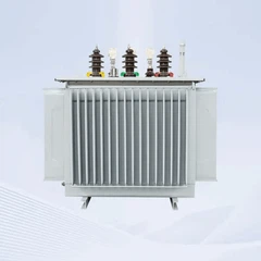
5. Worked Example 1: 10kV Transformer Feeder (800 kVA)
Given: 10 kV distribution substation, 800 kVA dry-type transformer (Dyn11, uk% = 6), HV side circuit breaker + numerical relay. 10 kV busbar short-circuit level: Sk.max = 200 MVA (max), Sk.min = 160 MVA (min).
Step 1 - Rated current & CT selection
I_nT = S / (√3 × U) = 800 / (1.732 × 10) ≈ 46.2 A
CT primary selected at ~1.2–1.5 × rated: 46.2 × 1.5 ≈ 70 A → standard ratio 75/5 (n_CT = 15). Secondary rated current = 46.2 ÷ 15 ≈ 3.08 A.
Step 2 - "Through-fault current": LV bus fault reflected to HV
Using per-unit method (base Sb = 100 MVA, Ub = 10.5 kV, Ib ≈ 5.5 kA):
Xs* = Sb / Sk.max = 100 / 200 = 0.5
XT* = (uk% × Sb) / (100 × Sn) = (6 × 100) / (100 × 0.8) = 7.5
XΣ* = 0.5 + 7.5 = 8.0
Ik(3) LV→HV = Ib / XΣ* = 5.5 kA / 8.0 ≈ 687 A (max mode)
Minimum mode (Sk.min = 160 MVA): Xs* = 0.625, XΣ* = 8.125, Ik ≈ 677 A; two-phase fault = 677 × 0.866 ≈ 586 A (used later for sensitivity check).
This 687 A is the current that flows through the HV relay when the LV busbar has a three-phase fault. The instantaneous setting must be above this value to avoid racing the LV breaker.
Step 3 - Calculate each setting
① Instantaneous overcurrent - set above LV bus through-fault:
I_op.inst = K_rel × Ik(3) = 1.3 × 687 ≈ 893 A → round to 900 A
Secondary = 900 ÷ 15 = 60 A, t = 0 s
② Time-overcurrent - set above max load (full load + self-start 1.5):
I_op.OC = (K_rel × K_ss × I_nT) / K_re
= (1.2 × 1.5 × 46.2) / 0.9 ≈ 92.4 A → 93 A (≈ 2 × I_n)
Secondary = 93 ÷ 15 ≈ 6.2 A, t = 0.7 s (coordinated with LV main)
③ Overload - alarm:
I_op.OL = (1.05 × 46.2) / 0.9 ≈ 54 A (≈ 1.17 × I_nT), secondary ≈ 3.6 A
Delay 10 s, alarm only
④ Earth-fault - unearthed 10 kV system, busbar 3U₀:
3U₀ = 30 V (secondary), 5 s delay, alarm.
Step 4 - Sensitivity check (mandatory!)
Instantaneous: Ksen = Ik.min(2) at relay ÷ Iop.inst = 7600 ÷ 900 ≈ 8.4 ≥ 2 ✓
Time-OC: Ksen = 586 ÷ 93 ≈ 6.3 ≥ 1.5 ✓
(Relay terminal two-phase fault: at 160 MVA, 3-phase ≈ 8.8 kA × 0.866 ≈ 7.6 kA.)
Step 5 - Setting summary
| Protection | Primary setting | Secondary setting (enter into relay) | Delay | Output |
|---|---|---|---|---|
| Instantaneous overcurrent | ≈ 900 A | 60 A | 0 s | Trip |
| Time-overcurrent | ≈ 93 A | 6.2 A | 0.7 s | Trip |
| Overload | ≈ 54 A | 3.6 A | 10 s | Alarm |
| Busbar earth (3U₀) | - | 30 V | 5 s | Alarm |
Two reminders:
① In this example the system is strong (200 MVA), so the instantaneous primary value reaches ~19 × rated - that's the price of hiding from LV through-faults. Instantaneous only covers the source-side portion of the HV winding; deeper winding faults rely on time-overcurrent (0.7 s) and transformer body protection. For larger or critical transformers, add differential protection.
② If the system short-circuit level were lower, the instantaneous setting would be lower and its reach longer - you cannot copy settings from another installation.
Have a specific motor or transformer panel you need protection-coordinated?
Send us your single-line diagram, short-circuit data, and motor / transformer nameplate details. Our protection engineers will return a coordinated setting sheet and a matched switchgear offer - fully IEC-compliant, ready for FAT and site commissioning.
6. Common Pitfalls in the Field (Lessons from Real Sites)
- Calculating only primary values, forgetting to convert to secondary - or dividing the CT ratio the wrong way. Always cross-check: secondary × ratio = primary?
- Wrong reset coefficient. Electromagnetic ≈ 0.85 vs. numerical ≈ 0.9–0.95 - > 5% difference, enough to cause marginal misoperation.
- Not hiding from starting / inrush current. Motor starting current and transformer magnetizing inrush (6–8 × In, decaying in 0.1–0.5 s) are "normal large currents." If instantaneous / overcurrent doesn't ride them out, you get nuisance trips on every energization.
- No time grading → cascading trips. An upstream relay that trips before its downstream can black out an entire busbar - the classic, most expensive failure mode.
- Setting without sensitivity checking. Set the threshold too high and the relay simply won't "feel" a real fault - equipment burns while the relay does nothing.
- Not reading the relay manual. Different manufacturers mean different conventions: primary vs. secondary units, phase vs. line voltage, different inverse-time curve formulas. Wrong units = wrong settings.
- Forgetting function switches and logic. PT failure blocking, auto-reclose coordination, BZT interlock, breaker-close enable - correct numbers, wrong logic = still misoperation.
- No test after changing settings. Primary injection, secondary injection, and breaker trip tests are mandatory. After commissioning, verify phase sequence and zero-sequence polarity, and archive the calculation report + setting sheet.
Professional habit: Always follow the same workflow - given data → select CT/PT → short-circuit calculation → set each element → sensitivity check → setting sheet + calculation report. Never skip steps. The step you skip is the one that will show up in the incident report.

High-voltage switchgear protection settings, at the end of the day, are about classifying faults, defining a threshold and time for each, and verifying that the relay operates when it should and never when it shouldn't. Once you understand the "diagnostic table," every number on a setting sheet stops being mysterious - each one stands for a specific fault scenario.
Ready to Spec Your Next Switchgear Project?
We design, manufacture, and test medium-voltage switchgear panels with fully calculated and pre-loaded protection settings - delivered worldwide to EPCs, panel builders, and industrial end-users.
Send us your single-line diagram and short-circuit data. Our engineers will respond with a technical proposal and quotation within 24 working hours.
Send Inquiry