


Complete Analysis of Test for Oil-Immersed Power Transformers
Apr 02, 2026
Leave a message
As the core hub equipment in power systems, the safe and stable operation of oil-immersed power transformers directly determines the reliability of the entire power grid. High-quality transformers form the basis of stable power supply, and regular professional transformer testing is critical for identifying potential hazards in advance, preventing transformer failures, and extending transformer service life.
With years of in-depth experience in the power equipment industry, GNEE ELECTRIC systematically summarizes the test intervals, technical requirements and practical key points of the five core transformer tests in line with international industry standards and field operation and maintenance practices.

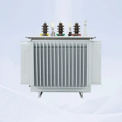
Oil-immersed Power Transformer
This article aims to help power engineering professionals conduct standardized transformer testing, strengthen the safety protection of transformer equipment, and ensure the stable operation of the power grid.
Measurement of Transformer Winding DC Resistance
DC resistance measurement is a core test to verify the integrity of the conductive circuits of power transformers, including transformer windings, transformer tap changers and transformer leads.
It is a mandatory test item for transformer operation and maintenance, which can effectively detect hidden defects such as transformer winding breakage, transformer turn-to-turn short circuit, poor contact of transformer tap changers, and inadequate welding of transformer leads.
Timely detection and handling of these defects can avoid serious transformer failures and ensure the normal operation of the transformer.
Transformer Test Intervals
- Routine test: every 1–3 years, or as specified by the enterprise's transformer operation and maintenance regulations
- Off‑circuit tap changer transformers: after adjusting the tap position of the transformer
- On‑load tap changer transformers: after the maintenance of the transformer tap changer (measure at all tap positions of the transformer)
- After major overhaul of the power transformer
- When necessary (e.g., after the transformer is subjected to short-circuit impact, abnormal operation of the transformer, etc.)
Key Transformer Test Points
All windings of the transformer shall be open‑circuited during the measurement. The DC resistance of each phase of the high-voltage (HV), medium-voltage (MV) and low-voltage (LV) windings of the transformer shall be measured separately, and the ambient temperature shall be recorded for the correction of test results.
The unbalance rate of the three-phase DC resistance of the transformer winding shall comply with the relevant standards: for transformers with a capacity of ≤1.6 MVA, the unbalance rate shall not exceed 4%; for transformers with a capacity of >1.6 MVA, the unbalance rate shall not exceed 2%.
If the deviation exceeds the standard, it indicates poor contact of the transformer tap changer or defective welding of the transformer winding joint, which requires further inspection and handling.
Measurement of Transformer Winding Insulation Resistance
Winding insulation resistance measurement is the most basic and widely used test item to evaluate the insulation condition of power transformers. It can effectively detect defects such as overall moisture of transformer windings, transformer insulation aging, and surface contamination of transformer windings.
At the same time, the moisture content of transformer insulation can be judged by the absorption ratio and polarization index of the transformer, which provides an important basis for the operation and maintenance of the transformer.

GNEE Transformer Factory, Mass Production
Transformer Test Intervals
- Routine test: every 1–3 years, or as specified by the enterprise's transformer operation and maintenance regulations
- After major overhaul of the power transformer
- When necessary (e.g., abnormal transformer oil quality, before the transformer is re-energized after outage, etc.)
Transformer Test Requirements
The insulation resistance value of the transformer winding shall be compared at the same temperature; if there is a significant drop compared with the previous test result, it indicates that the transformer insulation is damp or aging, and further inspection is required.
At an ambient temperature of 10–30°C, the absorption ratio (R60s/R15s) of the transformer winding shall not be less than 1.3, or the polarization index (R10min/R1min) shall not be less than 1.5. Failure to meet these values suggests that the transformer insulation has a dampness risk, which may affect the safe operation of the transformer.
Key Transformer Test Points
Before the test, all external leads of the transformer shall be disconnected, and the transformer core grounding wire shall be removed. A 2500V megohmmeter shall be used to measure the insulation resistance between each winding of the transformer and the ground, and between the windings of the transformer.
After the measurement, the transformer windings must be fully discharged to avoid safety hazards caused by residual charges or interference with the test results.
Measurement of Transformer Core Insulation Resistance
A power transformer core must have only one reliable earth point during normal operation. If the transformer core has multiple grounding points, it will create circulating currents, which will cause the transformer core to overheat and even lead to severe transformer faults.
The measurement of transformer core insulation resistance is a key test to detect transformer core grounding defects and ensure the normal operation of the transformer magnetic circuit.
Transformer Test Intervals
- Routine test: every 1–3 years, or as specified by the enterprise's transformer operation and maintenance regulations
- After major overhaul of the power transformer
- When necessary (e.g., the transformer light gas relay acts, abnormal dissolved gas in transformer oil, etc.)
Transformer Test Requirements
The test results of transformer core insulation resistance shall be stable compared with historical data; if there is a sharp drop, it indicates that the transformer core has multi-point grounding hidden dangers.
The operating core grounding current of the transformer is generally not greater than 0.1 A. If the current exceeds the standard, it indicates that the transformer has a multi-point grounding fault, and the transformer must be shut down immediately for inspection and maintenance.
Key Transformer Test Points
During the measurement, the external core grounding cable of the transformer shall be disconnected. A 1000V or 2500V megohmmeter shall be used to measure the insulation resistance between the transformer core and the ground.
Combined with the dissolved gas analysis (DGA) of transformer oil, it can accurately identify the type and severity of the transformer core fault, providing a basis for targeted maintenance.
Explore GNEE Transformer Products
Voltage Ratio Measurement at All Transformer Winding Taps
Voltage ratio testing is a core test to verify the correctness of the number of transformer winding turns and the position of the transformer tap changer. It can effectively detect defects such as transformer winding errors, misplaced transformer taps, and wrong connection of transformer leads, ensuring that the transformer ratio matches the nameplate data, and avoiding problems such as abnormal transformer voltage and excessive circulating current during the operation of the power transformer.
Transformer Test Intervals
- After disassembly and reconnection of the transformer tap leads
- After the replacement of the transformer winding
- When necessary (e.g., after the transformer is overhauled, after the transformer is transported, etc.)
Transformer Test Requirements
The measured voltage ratio of each corresponding joint of the transformer shall be consistent with the nameplate value and comply with the tap ratio regulations of the transformer.
For transformers with a voltage of <35 kV and a ratio of <3, the allowable deviation of the voltage ratio is ±1%; for all other transformers, the allowable deviation of the voltage ratio at the rated tap is ±0.5%, and the voltage ratio at other taps shall be within 1/10 of the transformer impedance voltage (%), with a maximum of ±1%.
Key Transformer Test Points
The test must be performed at all tap positions of the transformer. The three-phase voltage ratio of the transformer shall be measured step by step, and the corresponding relationship between the position of the transformer tap changer and the voltage ratio shall be focused on checking.
If the deviation exceeds the standard, it indicates mechanical faults of the transformer tap changer or incorrect number of transformer winding turns, which requires timely inspection and handling.
Full‑Voltage No‑Load Closing Test of Power Transformers
The full-voltage no-load closing test is an important test to verify the mechanical strength of the transformer winding, the insulation performance of the transformer, and the reliability of the transformer relay protection action. It is mainly used to check the anti-short-circuit capability of the power transformer and detect hidden dangers such as transformer winding deformation and transformer insulation defects. This test is only performed after the replacement of the transformer winding.
Transformer Test Intervals
- After the replacement of the transformer winding
Transformer Test Requirements
Complete replacement of transformer winding: 5 no-load closures, with an interval of 5 minutes each time
Partial replacement of transformer winding: 3 no-load closures, with an interval of 5 minutes each time
Key Transformer Test Points
The test shall be carried out at the rated voltage of the transformer. During the closing process, the inrush current of the transformer and the operation of the relay protection shall be closely monitored.
If maloperation of the relay protection, abnormal noise of the transformer, abnormal oil level of the transformer and other phenomena occur, the test shall be stopped immediately, and the transformer winding deformation, transformer insulation fault and other problems shall be inspected.
After the test, the oil level, noise and temperature of the transformer shall be checked before the transformer is put into operation.

Transformer Structure Diagram
Summary of Transformer Test & Maintenance and GNEE ELECTRIC Technical Support
Transformer testing is the "physical examination" for the safe operation of power transformers. It is essential to strictly comply with the transformer test intervals and technical requirements, and carry out each transformer test in a standardized manner.
At the same time, combined with transformer oil dissolved gas analysis (DGA) and transformer infrared temperature measurement, a comprehensive transformer condition monitoring system can be established to achieve early detection and early handling of transformer hidden dangers, and ensure the long-term stable operation of the transformer.
As a professional power equipment supplier, all oil‑immersed power transformers and dry-type transformers manufactured by GNEE ELECTRIC undergo complete type tests and factory tests before delivery, fully meeting international standards such as IEC and IEEE. We provide global customers with one-stop services including transformer test technical guidance, transformer operation and maintenance training, and transformer fault diagnosis, helping power enterprises improve the level of transformer operation and maintenance and ensure the stability of the power grid.
GNEE ELECTRIC is committed to providing high-quality transformer products and professional technical services. Whether you need to select a suitable power transformer, understand the details of transformer test technology, or solve transformer operation and maintenance problems, our professional team is always ready to serve you.
|
Rated Capacity(kVA) |
Voltage Combination |
Vector group |
No-load Loss(kW) |
Load Loss(kW) |
No-load Current(%) |
Short-Circuit Impedance(%) |
||
|
High Voltage(kV) |
High Voltage Tapping Range(%) |
Low Voltage(LV) |
||||||
|
30 |
20 |
±2×2.5 or ±5 |
0.4 |
Dyn11 or Yan11 or |
0.08 |
0.66/0.63 |
1.7 |
5.5 |
|
50 |
0.1 |
0.96/0.91 |
1.6 |
|||||
|
63 |
0.12 |
1.14/1.09 |
1.5 |
|||||
|
80 |
0.14 |
1.37/1.30 |
1.4 |
|||||
|
100 |
0.16 |
1.64/1.57 |
1.2 |
|||||
|
125 |
0.19 |
1.98/1.88 |
1.2 |
|||||
|
160 |
0.23 |
2.41/2.30 |
1.1 |
|||||
|
200 |
0.27 |
2.85/2.72 |
1 |
|||||
|
250 |
0.32 |
3.34/3.18 |
0.96 |
|||||
|
315 |
0.38 |
4.00/3.81 |
0.88 |
|||||
|
400 |
0.46 |
4.72/4.39 |
0.8 |
|||||
|
500 |
0.54 |
5.64/5.48 |
0.8 |
|||||
|
630 |
0.65 |
6.48 |
0.72 |
|||||
|
800 |
0.78 |
7.84 |
0.64 |
|||||
|
1000 |
0.92 |
10.7 |
0.56 |
6 |
||||
|
1250 |
1.1 |
12.5 |
0.56 |
|||||
|
1600 |
1.33 |
15.1 |
0.48 |
|||||
|
2000 |
1.56 |
19.1 |
0.48 |
|||||
|
2500 |
1.87 |
22.2 |
0.4 |
|||||
Send Inquiry