


How to calculate the impedance of a large power transformer?
Sep 22, 2025
Leave a message
Calculating the impedance of a large power transformer is a crucial aspect in the electrical power industry. As a supplier of large power transformers, understanding and accurately determining the impedance is essential for ensuring the proper operation, safety, and efficiency of power systems. In this blog, we will delve into the details of how to calculate the impedance of a large power transformer.
Understanding Transformer Impedance
Transformer impedance is a measure of the opposition to the flow of alternating current (AC) in a transformer. It is a complex quantity, consisting of both resistance and reactance components. The impedance of a transformer plays a vital role in determining the short - circuit current, voltage regulation, and parallel operation of transformers.
The impedance of a transformer is usually expressed as a percentage. The percentage impedance is defined as the voltage drop across the transformer windings at full - load current, expressed as a percentage of the rated voltage. For example, if a transformer has a percentage impedance of 5%, it means that when the transformer is carrying full - load current, the voltage drop across its windings is 5% of the rated voltage.
Factors Affecting Transformer Impedance
Several factors influence the impedance of a large power transformer:
- Winding Design: The number of turns, the cross - sectional area of the conductors, and the arrangement of the windings (such as concentric or interleaved) have a significant impact on the impedance. A larger number of turns or a smaller cross - sectional area of the conductors will generally increase the impedance.
- Core Material and Geometry: The type of core material (e.g., silicon steel) and its dimensions affect the magnetic flux path and, consequently, the reactance component of the impedance. A well - designed core can help optimize the impedance characteristics.
- Leakage Flux: Leakage flux is the magnetic flux that does not link both the primary and secondary windings. It is responsible for the reactive component of the impedance. The amount of leakage flux depends on the physical arrangement of the windings and the core.
Methods for Calculating Transformer Impedance
Theoretical Calculation
The theoretical calculation of transformer impedance involves using electromagnetic field theory and circuit analysis.
- Resistance Calculation:
The resistance of the transformer windings can be calculated using the formula (R=\rho\frac{l}{A}), where (\rho) is the resistivity of the conductor material, (l) is the length of the conductor, and (A) is the cross - sectional area of the conductor. For a large power transformer, the resistance of the primary and secondary windings is usually measured at DC and then adjusted for AC operation considering the skin effect and proximity effect. - Reactance Calculation:
The reactance of the transformer is mainly due to the leakage inductance. The leakage inductance can be calculated using complex electromagnetic field equations. For a simplified approach, the leakage inductance (L) can be estimated based on the physical dimensions of the windings and the core. The reactance (X = 2\pi fL), where (f) is the frequency of the AC supply.
The total impedance (Z) of the transformer is then calculated using the formula (Z=\sqrt{R^{2}+X^{2}}).
Experimental Measurement
Experimental measurement is a more practical and accurate way to determine the impedance of a large power transformer.
- Short - Circuit Test:
In a short - circuit test, the secondary winding of the transformer is short - circuited, and a reduced voltage is applied to the primary winding such that the rated current flows through the windings. The applied voltage (V_{sc}), the current (I_{sc}), and the power (P_{sc}) are measured.
The impedance (Z_{sc}) can be calculated as (Z_{sc}=\frac{V_{sc}}{I_{sc}}). The resistance (R_{sc}=\frac{P_{sc}}{I_{sc}^{2}}), and the reactance (X_{sc}=\sqrt{Z_{sc}^{2}-R_{sc}^{2}}).
The percentage impedance (Z_{p}) is calculated as (Z_{p}=\frac{V_{sc}}{V_{rated}}\times100%), where (V_{rated}) is the rated voltage of the primary winding.
Importance of Accurate Impedance Calculation
Accurate impedance calculation is of utmost importance for large power transformers:
- Short - Circuit Current Calculation: Knowing the impedance is essential for calculating the short - circuit current in the power system. This information is crucial for the proper sizing of circuit breakers, fuses, and other protective devices.
- Voltage Regulation: The impedance affects the voltage regulation of the transformer. A transformer with a lower impedance will have better voltage regulation, ensuring a more stable output voltage under varying load conditions.
- Parallel Operation: When multiple transformers are operated in parallel, their impedance values must be closely matched to ensure proper load sharing. If the impedance values are significantly different, one transformer may carry more load than the others, leading to overloading and potential damage.
Our Product Range and Impedance Considerations
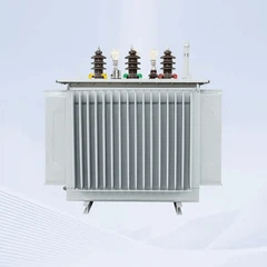
As a large power transformer supplier, we offer a wide range of high - quality transformers, including the 160kVA Copper Core Oil Immersed Power Transformer, the 420kVA Step Down Electric Transformer, and the Step Down Oil Immersed Power Transformer 11kv 1000kVA Hot Selling.
For each of our transformers, we carefully design and calculate the impedance to meet the specific requirements of our customers. Our engineering team uses advanced software and experimental techniques to ensure accurate impedance values, which in turn guarantee the reliable and efficient operation of our transformers in various power systems.
Conclusion
Calculating the impedance of a large power transformer is a complex but essential task. Whether through theoretical calculations or experimental measurements, accurate impedance determination is crucial for the proper functioning of power systems. As a large power transformer supplier, we are committed to providing high - quality transformers with precisely calculated impedance values.

If you are in the market for a large power transformer and need more information about impedance or our product range, we invite you to contact us for procurement and further discussions. We look forward to serving your power needs.
References
- Grover, F. W. (1946). Inductance Calculations: Working Formulas and Tables. Dover Publications.
- Stevenson, W. D. (1982). Elements of Power System Analysis. McGraw - Hill.
- Westinghouse Electric Corporation (1964). Electrical Transmission and Distribution Reference Book. Westinghouse Electric Corporation.
Send Inquiry