








Cooling System Structure and Thermal Management of 2000 kVA Oil Filled Transformers
May 11, 2026
Leave a message
GNEE is a specialized power equipment manufacturer and direct factory supplier of oil filled transformers, with over 18 years of industry experience.We are not traders - we are the source.
Our factory designs, manufactures, and exports high-performance 2000 kVA oil filled transformers to over 150 countries, serving utilities, industrial facilities, and renewable energy projects worldwide.
All products comply with IEC 60076, ISO 9001, and CE certification standards, ensuring reliable thermal management and long service life for every unit we deliver.


GNEE factory workshop - 2000 kVA oil filled transformers
1. Understanding the Cooling System Structure of 2000 kVA Oil Filled Transformers
The cooling system structure of 2000 kVA oil filled transformers is fundamental to ensuring operational reliability and longevity
In a 2000 kVA oil filled transformer, mineral insulating oil serves a dual function - it provides dielectric insulation between windings and core components while simultaneously acting as the primary heat transfer medium.
Heat generated by copper windings and the silicon steel core during electromagnetic conversion is absorbed by the surrounding oil, which then circulates through the cooling system structure to dissipate thermal energy into the ambient environment.
Without an efficiently designed cooling system structure, winding hot spot temperatures would rapidly exceed safe limits, accelerating insulation aging and potentially causing catastrophic failure.

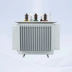
The cooling system structure of a 2000 kVA oil filled transformer typically comprises several interconnected components: the main steel tank housing the core and winding assembly, panel-type or tubular radiators mounted on the tank exterior, oil expansion conservator vessels, and protective monitoring devices such as temperature indicators and pressure relief valves.
In forced-cooling configurations, the cooling system structure also integrates electric fans or oil circulation pumps to enhance heat dissipation capacity beyond what natural convection alone can achieve.
Each component within this cooling system structure plays a critical role in maintaining the thermal equilibrium that keeps the transformer operating within its designed temperature limits.
2. Core Cooling Methods: ONAN and ONAF for 2000 kVA Oil Filled Transformer Thermal Management
Effective thermal management of 2000 kVA oil filled transformers relies primarily on two standardized cooling methods: ONAN (Oil Natural Air Natural) and ONAF (Oil Natural Air Forced). Understanding the distinction between these methods is essential for selecting the optimal cooling system structure for specific installation environments and load profiles.

ONAN Cooling in 2000 kVA Oil Filled Transformers

ONAN represents the baseline passive cooling system structure, where oil circulates naturally through thermal convection without any mechanical assistance.
As the windings and core heat the surrounding oil, its density decreases, causing it to rise to the top of the tank and enter the radiator panels. There, the oil transfers heat through the radiator walls to the surrounding air, cools, becomes denser, and descends back to the bottom of the tank - creating a continuous natural circulation loop.

ONAN cooling system structures are simple, highly reliable, and require minimal maintenance, making them suitable for 2000 kVA oil filled transformers operating under stable, moderate load conditions.
However, during sustained high-load or high-ambient-temperature scenarios, ONAN alone may not provide sufficient cooling capacity.
ONAF Cooling in 2000 kVA Oil Filled Transformers

When enhanced thermal management is required, the ONAF cooling method supplements the natural oil circulation with forced air flow generated by electric fans mounted adjacent to the radiators.
The fans increase the rate of convective heat transfer from the radiator surfaces to the ambient air, improving cooling efficiency by approximately 150–200% compared to ONAN alone.
This effectively increases the transformer's load-carrying capability by 20–40% without requiring a larger tank or radiator surface area.
For 2000 kVA oil filled transformers, ONAF cooling is commonly deployed in industrial substations where load fluctuations are frequent and ambient temperatures may be elevated.
3. Heat Dissipation Mechanisms and Radiator Design in the Cooling System Structure
The radiator design within the cooling system structure of 2000 kVA oil filled transformers directly determines how effectively heat is transferred from the insulating oil to the external environment. Radiators are typically manufactured as detachable panel-type or tubular assemblies, connected to the main tank through top and bottom headers using flanged joints. This modular cooling system structure allows for flexible configuration - additional radiator panels can be added to increase cooling capacity for transformers destined for hot climates or high-duty-cycle applications.
Within the cooling system structure, the heat dissipation process follows established thermodynamic principles. Hot oil entering the radiator from the top header flows downward through multiple parallel channels, each maximizing surface area contact with the cooler ambient air. The temperature differential between the oil and the surrounding air drives heat transfer across the radiator wall. Computational Fluid Dynamics (CFD) analysis has demonstrated that optimized radiator designs - including parameters such as panel height, fin spacing, and fin count - can improve cooling efficiency by over 27% while simultaneously reducing manufacturing costs per kilowatt of cooling capacity. For 2000 kVA oil filled transformers, well-designed radiators are critical to preventing excessive top-oil temperature rise and protecting winding insulation integrity.
4. Thermal Management Strategies for Hot Spot Temperature Control in 2000 kVA Oil Filled Transformers
Hot spot temperature - the highest temperature point within the winding insulation system - is the single most critical parameter governing insulation life and transformer reliability. International standards such as IEC 60076 specify that for mineral-oil-immersed transformers, the average winding temperature rise should not exceed 65 K, with top-oil temperature rise limited to 55 K under rated conditions. For 2000 kVA oil filled transformers, effective thermal management must ensure that hot spot temperatures remain within these specified limits under all anticipated operating scenarios.
Thermal management strategies for 2000 kVA oil filled transformers encompass several key approaches.
- First, optimizing internal oil flow paths through proper winding duct design ensures that cooling oil reaches all heat-generating regions, preventing localized hot spot formation.
- Second, accurate calculation of heat generation distribution - considering both load-dependent copper losses (I²R losses) and constant core losses (hysteresis and eddy current losses) - enables precise prediction of temperature profiles throughout the transformer.
- Third, in ONAF configurations, strategic fan placement and airflow management prevent uneven cooling that could create thermal imbalances across different phases.
Research has shown that through systematic optimization of cooling system structure parameters, winding hot spot temperatures can be reduced significantly - in some documented cases from 78.1°C to 60.7°C, representing a 22.3% reduction. Such improvements in thermal management directly translate to extended insulation life and enhanced overload capability for 2000 kVA oil filled transformers.
5. Technical Parameters: 2000 kVA Oil Filled Transformer Cooling System Performance
The following technical parameter table summarizes the key specifications for the cooling system structure and thermal management of a standard 2000 kVA oil filled transformer manufactured by GNEE. All values comply with IEC 60076 standards and can be customized based on specific project requirements.
| Parameter | Specification |
|---|---|
| Rated Capacity | 2000 kVA |
| Phase | Three Phase |
| Primary Voltage | 6 kV / 10 kV / 11 kV / 20 kV / 33 kV / 35 kV (customizable) |
| Secondary Voltage | 0.4 kV / 0.415 kV / 0.69 kV (customizable) |
| Frequency | 50 Hz / 60 Hz |
| Cooling Method | ONAN / ONAF |
| Winding Material | Electrolytic Copper (high-purity) |
| Core Material | Cold-Rolled Grain-Oriented (CRGO) Silicon Steel |
| Vector Group | Dyn11 / Yyn0 (customer-specified) |
| Insulation Class | Class A (105°C) |
| Top Oil Temperature Rise | ≤ 55 K (IEC 60076) |
| Average Winding Temperature Rise | ≤ 65 K (IEC 60076) |
| Winding Hot Spot Temperature Limit | ≤ 98°C (under rated conditions) |
| No-Load Loss | ≤ 2200 W (typical, copper winding) |
| Load Loss (75°C) | ≤ 14500 W (typical, copper winding) |
| Efficiency | ≥ 98.5% |
| Impedance Voltage | 4.5% – 6.0% |
| Noise Level | ≤ 65 dB |
| Cooling Radiator Type | Detachable panel-type / corrugated fin wall |
| Temperature Monitoring | Dial oil temperature indicator + optional fiber optic sensors |
| Protection Devices | Buchholz relay, pressure relief valve, magnetic oil level gauge |
| Standards Compliance | IEC 60076, ISO 9001, CE |
6. Applications and Environmental Adaptability of 2000 kVA Oil Filled Transformer Cooling Systems
The cooling system structure of 2000 kVA oil filled transformers must be designed to function reliably across diverse application environments, from temperature-controlled indoor substations to harsh outdoor installations. In industrial distribution substations serving manufacturing plants, mining operations, and chemical facilities, the cooling system faces high and often fluctuating loads. The thermal inertia of the oil-filled cooling system structure provides inherent resilience against short-term overloads, allowing the transformer to absorb load surges without immediate temperature excursion.
For renewable energy applications - such as solar photovoltaic farms and wind power collection substations - 2000 kVA oil filled transformers operate under variable generation profiles where thermal cycling is more pronounced than in steady-state grid applications. The cooling system structure must accommodate these cyclical temperature variations without excessive thermal stress on insulation materials or gasket seals.
In urban power distribution networks, where transformers are often installed near residential or commercial areas, the cooling system structure design must also address acoustic performance - keeping operating noise below regulatory limits.
Conclusion
The cooling system structure and thermal management of 2000 kVA oil filled transformers are not peripheral design considerations - they are central to transformer performance, reliability, and service life. From the fundamental ONAN/ONAF cooling methods and radiator heat dissipation mechanisms to advanced hot spot temperature control and IoT-enabled thermal monitoring, every element of the cooling system structure works together to ensure that critical winding insulation remains protected under all operating conditions.
At GNEE, we bring over 18 years of transformer manufacturing experience to every 2000 kVA oil filled transformer we deliver. Whether your project requires an ONAN-cooled unit for a stable grid distribution application or an ONAF-configured transformer for a high-demand industrial substation, our engineering team is ready to design and manufacture a solution tailored to your specifications. All transformers are built to international standards, rigorously tested for thermal performance, and shipped with complete quality documentation.
Looking for a reliable, factory-direct 2000 kVA oil filled transformer with a proven cooling system structure? Contact GNEE today - send us your specifications and receive a customized quotation within 24 hours. Let our expertise in transformer thermal management power your next project with confidence.
What is the specification of 2000 KVA transformer?
The document provides specifications for a 2000 KVA transformer. It has an ONAN cooling type, operates at 11,000V high voltage and 433V low voltage, with a frequency of 50Hz. The total weight is 5935kg with a core and winding weight of 2575kg and oil volume of 1488L.
What is the cooling system of a transformer?
The following two transformer cooling methods are adopted in dry-type transformers. Air Natural (AN) cooling – Cooled by surrounding air. Heat transfer by natural air convection. Air Force (AF) cooling – Forced air circulation using fans and blowers.
How much oil is in a 2000 KVA transformer?
The oil capacity of a 2000 kVA oil-filled transformer is generally around 1300 to 1500 liters. This can vary depending on the specific design and manufacturer specifications.
How much insulating oil is used in a 2000 kVA oil filled transformer?
A standard 2000 kVA oil immersed transformer typically contains around 1200 to 2500 liters of transformer oil. The exact oil quantity depends on radiator configuration, cooling design, voltage class, and manufacturer specifications.
What voltages are commonly available for a 2000 kVA transformer?
The most common primary voltages are 11kV, 13.8kV, 15kV, 20kV, 22kV, and 33kV, while common secondary voltages include 400V, 415V, 440V, 480V, and 690V. Customized voltage combinations can also be produced according to project requirements.
Which is better, an oil type or dry type transformer?
Oil immersed transformers are generally preferred for outdoor installations and high-capacity industrial applications because they offer better cooling efficiency, stronger overload capability, and longer service life. Dry type transformers are usually selected for indoor use because they provide better fire safety, lower environmental risk, and simpler maintenance.
Send Inquiry