







What is an Energy Storage Containerized Step-up Substation?
Aug 10, 2026
Leave a message
What is an Energy Storage Containerized Step-up Substation?
The energy storage containerized step-up substation is a highly modular and complete set of power transformation equipment, which steps up the low-voltage AC power output from the energy storage PCS (Power Conversion System) to the medium voltage level, realizing safe and stable grid-connection of the energy storage system.
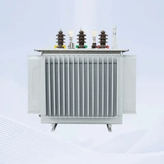
The complete equipment is arranged inside a standard container cabin, with core configurations including oil-immersed transformer, medium voltage switchgear, communication & power supply cabinet, and frame circuit breaker cabinet. All equipment completes assembly, wiring and whole-machine factory commissioning in the factory. Different from the traditional model of decentralized procurement and on-site step-by-step installation, it greatly reduces on-site construction workload and lowers the risk of multi-equipment docking.


We provide two mainstream topology layouts to adapt to different project conditions:
- Centralized PCS Layout: Suitable for large-scale grid-level energy storage power stations, with high power density, centralized scheduling and obvious comprehensive investment advantages;
- String PCS Layout: Excellent system redundancy, no whole-station shutdown caused by single branch fault, widely used in distributed energy storage, solar-storage integrated power stations and microgrid projects.
Not sure which topology fits your project better?
Share your site capacity, grid‑connection requirements and operation goals with GNEE Electric, our engineering team will recommend the most cost‑effective layout solution for your specific case.
Core Advantages of GNEE Electric Energy Storage Containerized Step-up Substation
Integrated Containerized Prefabrication, Fast Delivery & Commissioning
- Adopt standard container dimensions, compatible with global sea and land transportation conditions;
- Oil-immersed transformer, medium voltage switchgear, frame circuit breaker cabinet and communication & power supply cabinet are uniformly arranged in the cabin, with complete factory assembly and commissioning;
- Only cable docking is required on site, no complex secondary wiring and commissioning;
- Compared with the traditional decentralized power station construction model, it significantly shortens the project construction cycle, and saves on-site civil engineering, installation labor and other costs.
Intelligent Monitoring, Remote Digital O&M
- Real-time collection of operating status of oil-immersed transformer, medium voltage switchgear, frame circuit breaker cabinet and PCS, online monitoring of key electrical parameters such as voltage, current, power and temperature;
- Support remote access to all operating data in the containerized step-up substation, and remote completion of circuit breaker opening and closing control;
- Equipped with standardized communication interfaces, realize signal convergence relying on the communication & power supply cabinet, and seamlessly dock with EMS (Energy Management System) and SCADA (Supervisory Control And Data Acquisition) platform to realize remote centralized management and control.
Rugged Cabin Structure, Adaptable to All Kinds of Harsh Outdoor Environments
- The container cabin has high structural strength, suitable for long-term outdoor open-air arrangement;
- The protection level of the electrical cabin reaches IP54~IP55, with complete dustproof and waterproof design;
- Support C3~C5 medium anti-corrosion configuration, which can cope with high and low temperature, sand dust, coastal light salt spray environment;
- Standard operating temperature range: -25℃~60℃, heat dissipation optimization scheme can be matched for high temperature areas;
- Standard applicable altitude: ≤1000m, special upgrade of insulation and heat dissipation can be carried out for high altitude scenarios up to ≤3000m;
- SF₆-free environmental protection scheme is optional for medium voltage switchgear, which meets the needs of low-carbon projects.
Zoned Professional Thermal Management, Ensuring Efficient and Stable Operation of Equipment
The container adopts zoned heat dissipation design, and optimizes the air duct layout relying on fluid simulation:
- Transformer area: The oil-immersed transformer adopts ONAN oil-immersed self-cooling heat dissipation;
- Cabinet area: The medium voltage switchgear, frame circuit breaker cabinet and communication & power supply cabinet adopt ventilation and heat dissipation scheme;
- Reasonably isolate the mutual interference of heat from various equipment, reduce the aging speed of equipment, extend the service life of the whole set of devices, and the transformer operating efficiency ≥99%.
Multi-level Perfect Protection, Building a Solid Barrier for Grid-connection Safety
The oil-immersed transformer is equipped with complete body protection including oil temperature, oil level, pressure release and gas protection;
- The relay protection is configured with overcurrent and ground fault protection functions;
- The frame circuit breaker cabinet realizes overload, short circuit and leakage protection on the low voltage side;
- The medium voltage switchgear has internal arc fault withstand capability, and optional surge lightning protection device;
- The complete set of protection logic is uniformly set, and the protection of each cabinet cooperates with each other to realize fast fault isolation.
Images of our step up skid station for BESS

Components of a GNEE Electric energy storage step up station

Network application of GNEE Electric's step-up skid station for BESS

Diagram example of step-up skid station with central PCS

Diagram example of step-up skid station with string PCS


Exterior dimensions

For ease of transportation, the station has the same dimensions as a 20-foot container: W 6,058mm x H 2,896mm x D 2,438mm.
Internal composition

Technical data
Power Transformer for Energy Storage – Technical Data
| Parameter | 3,000 kVA | 5,000 kVA |
|---|---|---|
| Transformer Type | Oil-Immersed Transformer | Oil-Immersed Transformer |
| Rated Power | 3,000 kVA @ 40℃ (Note 1) | 5,000 kVA @ 40℃ (Note 1) |
| Maximum Power | 3,400 kVA @ 30℃ | 5,500 kVA @ 30℃ |
| Vector Group | Dy11 | Dy11 + Dy11 (Dual LV Winding) |
| LV/MV Voltage | 0.8 kV / 20–35 kV | 0.8 kV / 20–35 kV |
| Maximum LV Current at Rated Voltage | 2,500 A × 1 | 2,500 A × 2 |
| Frequency | 50 Hz | 50 Hz |
| HV Tap Changer | ±2 × 2.5% | ±2 × 2.5% |
| Efficiency | ≥99% | ≥99% |
| Cooling Type | ONAN (Oil Natural Air Natural) | ONAN (Oil Natural Air Natural) |
| Impedance Voltage | 6.5% (±10%) | 6.5% (±10%) |
| Insulating Oil | PCB-Free Mineral Oil | PCB-Free Mineral Oil |
| Winding Material | Al/Al | Al/Al |
| Insulation Class | Class A | Class A |
| Temperature Rise | 65 K | 65 K |
MV Switchgear for Energy Storage – Technical Data
| Parameter | 3,000 kVA | 5,000 kVA |
|---|---|---|
| Switchgear Type | MV Switchgear with SF₆-Free Insulation | MV Switchgear with SF₆-Free Insulation |
| Rated Voltage | 24–36 kV (Note 2) | 24–36 kV (Note 2) |
| Rated Current | 630 A | 630 A |
| Internal Arc Classification | IAC AFLR 31.5 kA / 1 s | IAC AFLR 31.5 kA / 1 s |
| Number of Feeders | 2–3 Feeders | 2–3 Feeders |
| Vacuum Circuit Breaker | Included | Included |
| MV Surge Arrester | Optional (Note 3) | Optional (Note 3) |
PCS for Energy Storage – Technical Data
| Parameter | 3,000 kVA | 5,000 kVA |
|---|---|---|
| DC Input Voltage Range | 800–1500 V | 1300–1500 V |
| Maximum DC Input Current | 1,935 A × 2 | 2,154 A × 2 |
| Number of DC Inputs | 2 Inputs | 2 Inputs |
| AC Output Rating | 3,000 kVA / 690 V | 5,000 kVA / 800–900 V |
| PCS Configuration | Centralized PCS / String PCS Optional | Centralized PCS / String PCS Optional |
Protection System for Energy Storage – Technical Data
| Parameter | 3,000 kVA | 5,000 kVA |
|---|---|---|
| AC Input Protection | Circuit Breaker | Circuit Breaker |
| Transformer Protection | Oil Temperature, Oil Level, Oil Pressure, Buchholz Relay | Oil Temperature, Oil Level, Oil Pressure, Buchholz Relay |
| Relay Protection | 50/51, 50N/51N | 50/51, 50N/51N |
| LV Surge Protection | AC Type II (Optional: AC Type I + II) | AC Type II (Optional: AC Type I + II) |
| Anti-Rodent Protection | Available | Available |
| Corrosion Protection | C5-M Medium (Optional) | C5-M Medium (Optional) |
General Step-up Station – Technical Data
| Parameter | 3,000 kVA | 5,000 kVA |
|---|---|---|
| Container Dimensions (W × H × D) | 6,058 mm × 2,896 mm × 2,438 mm | 6,058 mm × 2,896 mm × 2,438 mm |
| Approximate Weight | ≤18 t | ≤22 t |
| Operating Temperature Range | -25℃ to +60℃ (Note 4) | -25℃ to +60℃ (Note 4) |
| Auxiliary Power Supply | 400 V AC (Capacity According to Project Requirements) | 400 V AC (Capacity According to Project Requirements) |
| UPS | 2 kVA UPS Optional (Note 3) | 2 kVA UPS Optional (Note 3) |
| Degree of Protection | IP54 | IP54 |
| Relative Humidity | 0–95% (Non-Condensing) | 0–95% (Non-Condensing) |
| Operating Altitude | ≤1,000 m Standard; Higher Altitude Available with Customized Design (Note 5) | ≤1,000 m Standard; Higher Altitude Available with Customized Design (Note 5) |
| Communication Interface | RS485, Ethernet, Optical Fiber | RS485, Ethernet, Optical Fiber |
| Applicable Standards | IEC 60076, IEC 62271-200, IEC 62271-202, IEC 61439-1, EN 50588-1 | IEC 60076, IEC 62271-200, IEC 62271-202, IEC 61439-1, EN 50588-1 |
All above parameters serve as standard reference. Voltage class, capacity, anti‑corrosion grade and protection configuration can be fully customized for your local grid codes and site environmental conditions.
Send us your project brief, and we will deliver tailored datasheet, single‑line diagram and competitive quotation within 24 working hours.
Get Custom Datasheet & Quotation
Typical Application Scenarios of Energy Storage Containerized Step-up Substation
- Large-scale independent grid-level energy storage power stations
- Solar-storage and wind-storage integrated new energy projects
- Industrial and commercial user-side energy storage (peak-valley arbitrage, demand control)
- Island power supply and remote area microgrid energy storage systems
- Grid auxiliary service energy storage projects (frequency regulation, voltage regulation)

GNEE Electric energy storage containerized step-up substations have been implemented in multiple energy storage projects in Australia, Southeast Asia, Europe and Africa. We can cooperate with global EPC general contractors to deliver economical energy storage grid-connection solutions that meet local grid specifications.
Why Choose GNEE Electric Energy Storage Containerized Step-up Substation?
GNEE Electric focuses on the R&D and export of transformers and new energy power transformation equipment, providing one-stop complete solutions for global energy storage investors and EPC enterprises:
✅ Flexible Scheme Customization: Centralized/string PCS architecture, voltage level, anti-corrosion level and protection configuration can be adjusted according to project demands;
✅ Complete Factory Delivery: Integrated assembly and commissioning of oil-immersed transformer, medium voltage switchgear, ACB panel and communication & power supply cabinet;
✅ Rigorous Factory Test: Complete with full set of drawings, test reports and certification materials to meet grid-connection review requirements;
✅ Full-cycle Technical Support: Pre-sales scheme design, production follow-up, on-site commissioning technical guidance;
✅ Large-scale Production Guarantee: Stable and controllable delivery cycle for large-volume orders.
At present, containerized step-up substations have become the mainstream choice for energy storage grid-connection, as energy storage projects generally pursue shortening the construction period, simplifying on-site construction and reducing operation and maintenance difficulty.
If you are planning an energy storage project and looking for a reliable supplier of integrated step-up complete equipment, welcome to contact GNEE Electric to obtain a special technical solution and detailed quotation.
Send Inquiry