









Why Is a 1600kVA 20kV/0.4kV Oil-Immersed Distribution Transformer with Advanced Cooling Design the Ideal Choice?
Aug 07, 2026
Leave a message
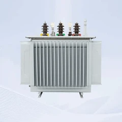
1600kVA 20kV/0.4kV Oil-Immersed Distribution Transformer is designed for reliable medium-voltage power distribution in industrial facilities, infrastructure projects, and commercial applications. Featuring an ONAN (Oil Natural Air Natural) cooling system, copper windings, and optimized heat dissipation design, this transformer effectively controls temperature rise, improves operational reliability, and extends service life under continuous load conditions.
With a rated capacity of 1600kVA, primary voltage of 20kV, and secondary voltage of 400V, it provides stable voltage conversion and efficient power distribution for demanding electrical systems. The advanced thermal management design helps reduce insulation aging risks and ensures long-term transformer performance.

Why Is Heat Dissipation Performance Important For A 1600kVA Distribution Transformer
A transformer converts electrical energy through electromagnetic induction, but energy conversion is always accompanied by power losses. These losses are mainly generated from:
1.Core losses (iron losses)
Core losses are the power losses generated in the transformer core when the transformer is energized. Unlike load-related losses, core losses occur continuously as long as the transformer is connected to the power supply, even when there is no load.

1.1Main Types of Core Losses
- Hysteresis Loss:
When alternating voltage is applied to the transformer core, the magnetic domains inside the core continuously change their direction in response to the alternating magnetic field. During repeated magnetization and demagnetization cycles, a portion of electrical energy is consumed and converted into heat, resulting in energy losses within the core material. This phenomenon is known as hysteresis loss. By using high-quality silicon steel sheets with improved magnetic properties, hysteresis losses can be effectively minimized, reducing overall core losses and improving transformer efficiency.
- Eddy Current Loss:
When an alternating magnetic field is applied to the transformer core, it induces circulating currents within the core material, which are known as eddy currents. These currents consume additional electrical energy and generate extra heat, resulting in increased transformer temperature rise and reduced operating efficiency. To minimize eddy current losses, modern transformers are designed with high-quality silicon steel sheets, laminated core structures, and insulated steel layers. These advanced core designs effectively reduce unnecessary energy losses, improve thermal performance, and enhance the overall efficiency and reliability of the transformer.

Impact of Core Losses on Transformer Temperature
Although core losses are usually lower than load losses, they exist continuously throughout transformer operation.
Insufficient heat dissipation caused by core losses may result in:
- Increased core temperature
- Higher oil temperature
- Higher overall transformer temperature rise
Therefore, large-capacity transformers such as 1600kVA units require optimized core design and effective cooling systems.
2.Copper losses (winding losses)
Copper losses are the power losses generated in transformer windings when electrical current flows through the conductor resistance.The electrical energy lost due to resistance is converted into heat.
The basic relationship is:
Electrical Energy → Heat Energy
Copper loss is calculated according to:
Pcu = I²R
Where:
Pcu = Copper loss
I = Load current
R = Winding resistance
This means that copper losses increase rapidly as the load current increases.
Factors Affecting Copper Losses
1.1Load Current
Load current is the most important factor affecting copper losses.
Examples:
- Low load operation → Lower winding temperature
- Full load operation → Higher winding temperature
- For a 1600kVA transformer, continuous high-load operation requires excellent cooling performance to control winding temperature.
1.2Winding Material
The winding material directly affects electrical resistance and heat generation.
Common materials include:
| Material | Characteristics |
|---|---|
| Copper | Low resistance, excellent conductivity and thermal performance |
| Aluminum | Lightweight and lower cost |
The 1600kVA transformer uses copper windings, providing:
- Lower resistance losses
- Reduced heat generation
- Better thermal conductivity
- Improved operating stability
1.3Operating Temperature
The resistance of transformer windings increases as temperature rises.
Higher temperature:
↓
Higher resistance
↓
Higher copper losses
↓
More heat generation
Therefore, effective cooling helps maintain lower winding temperature and reduce additional losses.
Reducing core losses and winding losses provides the following advantages:
| Benefits of Reducing Core Loss and Winding Loss | Description |
|---|---|
| Lower Temperature Rise | Reduces transformer operating temperature and improves thermal performance |
| Higher Efficiency | Minimizes energy losses and improves overall transformer efficiency |
| Longer Insulation Life | Reduces thermal stress on insulation materials and extends service life |
| Reduced Maintenance Cost | Decreases maintenance requirements and operating expenses |
| Improved Reliability | Enhances long-term operational stability and reliability |
1600kVA Transformer with Advanced Heat Dissipation Design
GNEE TRANSFORMER PARAMETER
|
Rated Capacity(kVA) |
Voltage Combination |
Vector group |
No-load Loss(kW) |
Load Loss(kW) |
No-load Current(%) |
Short-Circuit Impedance(%) |
||
|
High Voltage(kV) |
High Voltage Tapping Range(%) |
Low Voltage(LV) |
||||||
|
30 |
20 |
±2×2.5 or ±5 |
0.4 |
Dyn11 or Yan11 or |
0.08 |
0.66/0.63 |
1.7 |
5.5 |
|
50 |
0.1 |
0.96/0.91 |
1.6 |
|||||
|
63 |
0.12 |
1.14/1.09 |
1.5 |
|||||
|
80 |
0.14 |
1.37/1.30 |
1.4 |
|||||
|
100 |
0.16 |
1.64/1.57 |
1.2 |
|||||
|
125 |
0.19 |
1.98/1.88 |
1.2 |
|||||
|
160 |
0.23 |
2.41/2.30 |
1.1 |
|||||
|
200 |
0.27 |
2.85/2.72 |
1 |
|||||
|
250 |
0.32 |
3.34/3.18 |
0.96 |
|||||
|
315 |
0.38 |
4.00/3.81 |
0.88 |
|||||
|
400 |
0.46 |
4.72/4.39 |
0.8 |
|||||
|
500 |
0.54 |
5.64/5.48 |
0.8 |
|||||
|
630 |
0.65 |
6.48 |
0.72 |
|||||
|
800 |
0.78 |
7.84 |
0.64 |
|||||
|
1000 |
0.92 |
10.7 |
0.56 |
6 |
||||
|
1250 |
1.1 |
12.5 |
0.56 |
|||||
|
1600 |
1.33 |
15.1 |
0.48 |
|||||
|
2000 |
1.56 |
19.1 |
0.48 |
|||||
|
2500 |
1.87 |
22.2 |
0.4 |
|||||
At GNEE, a specialized factory of power transformer manufacturing heritage, we integrate low-voltage winding conductor transposition technology as a standard feature in all high‑capacity units. This advanced winding technique is the single most effective engineering measure to slash the eddy current loss of a 1600kVA oil‑immersed transformer, directly improving efficiency, lowering hot‑spot temperatures, and extending operational life.
Understanding the Cooling System Structure of 1600 kVA Oil Filled Transformers
The cooling system structure of 1600 kVA oil filled transformers is fundamental to ensuring operational reliability and longevity
In a 1600 kVA oil filled transformer, mineral insulating oil serves a dual function - it provides dielectric insulation between windings and core components while simultaneously acting as the primary heat transfer medium.
Heat generated by copper windings and the silicon steel core during electromagnetic conversion is absorbed by the surrounding oil, which then circulates through the cooling system structure to dissipate thermal energy into the ambient environment.
Without an efficiently designed cooling system structure, winding hot spot temperatures would rapidly exceed safe limits, accelerating insulation aging and potentially causing catastrophic failure.

In forced-cooling configurations, the cooling system structure also integrates oil circulation pumps to enhance heat dissipation capacity beyond what natural convection alone can achieve.
Core Cooling Methods: ONAN for 1600 kVA Oil Filled Transformer Thermal Management
Effective thermal management in a 1600 kVA oil-immersed transformer primarily depends on the ONAN cooling system. A thorough understanding of this cooling method is crucial for selecting the most suitable transformer according to the installation conditions and load requirements.

ONAN represents the baseline passive cooling system structure, where oil circulates naturally through thermal convection without any mechanical assistance.
As the windings and core heat the surrounding oil, its density decreases, causing it to rise to the top of the tank and enter the radiator panels. There, the oil transfers heat through the radiator walls to the surrounding air, cools, becomes denser, and descends back to the bottom of the tank - creating a continuous natural circulation loop.
ONAN cooling system structures are simple, highly reliable, and require minimal maintenance, making them suitable for 2000 kVA oil filled transformers operating under stable, moderate load conditions.
Heat Dissipation Mechanisms and Radiator Design in the Cooling System Structure
The radiator design within the cooling system structure of 2000 kVA oil filled transformers directly determines how effectively heat is transferred from the insulating oil to the external environment. Radiators are typically manufactured as detachable panel-type or tubular assemblies, connected to the main tank through top and bottom headers using flanged joints. This modular cooling system structure allows for flexible configuration - additional radiator panels can be added to increase cooling capacity for transformers destined for hot climates or high-duty-cycle applications.
Within the cooling system structure, the heat dissipation process follows established thermodynamic principles. Hot oil entering the radiator from the top header flows downward through multiple parallel channels, each maximizing surface area contact with the cooler ambient air. The temperature differential between the oil and the surrounding air drives heat transfer across the radiator wall. Computational Fluid Dynamics (CFD) analysis has demonstrated that optimized radiator designs - including parameters such as panel height, fin spacing, and fin count - can improve cooling efficiency by over 27% while simultaneously reducing manufacturing costs per kilowatt of cooling capacity. For 2000 kVA oil filled transformers, well-designed radiators are critical to preventing excessive top-oil temperature rise and protecting winding insulation integrity.
Why Choose GNEE's 1600kVA Oil-Immersed Transformer for Reliable Power Distribution?
Engineering Expertise That Protects Every Watt
At GNEE, we understand that a 1600kVA 20kV/0.4kV Oil-Immersed Distribution Transformer is a long-term investment-often expected to perform for 25 to 30 years with minimal intervention. That's why every transformer that leaves our factory undergoes rigorous routine tests (winding resistance, voltage ratio, impedance, dielectric strength) and optional type tests according to your requirements. Our copper winding technology, grain-oriented silicon steel cores, and precision vacuum oil-filling processes ensure that losses are kept to a minimum, so more of each kilowatt-hour you pay for actually reaches the office sockets. We embed decades of engineering refinement into every unit, from the conservator design preventing moisture ingress to the robust welded tank structure resisting corrosion and leaks.

Global Logistics and Factory-Direct Support
Choosing a GNEE 1600kVA 20kV/0.4kV Oil-Immersed Distribution Transformer means more than just getting quality hardware-it means gaining a partner who supports your project from technical drawing approval through sea freight delivery and after-sales commissioning guidance. We regularly ship oil-filled transformers up to 10 MVA to markets across Asia, Africa, the Middle East, and South America. Our export team manages secure seaworthy packaging, custom documentation, and partial discharge-free delivery logistics. For the same kilowatt-hour to travel reliably inside your country's grid, you need a transformer partner who values punctuality and compliance as much as you do. Our 600+ satisfied global clients testify to that commitment.
FAQ
1. How does natural cooling work in 1600kVA 20/0.4KV Oil-immersed Distribution Transformers?
Natural cooling relies on the natural movement of oil and air caused by temperature differences.
2.How does cooling affect transformer capacity and performance?
Cooling directly affects the maximum load a transformer can safely carry.
Better cooling allows:
- Higher MVA ratings
- Lower operating temperatures
- Reduced insulation aging
- Improved reliability
3.Why does a 1600kVA transformer need advanced cooling design?
A 1600kVA transformer generates more heat due to its higher capacity and continuous load operation. Advanced cooling design reduces temperature rise, improves reliability, and extends service life.
Send Inquiry