


A Comprehensive Guide to the Core Principles of Oil-Filled Power Transformers
Apr 01, 2026
Leave a message
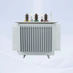
In power systems, oil-filled power transformers are indispensable core equipment that fulfill the critical functions of voltage conversion and power transmission. Widely used in power grids, industrial applications, and renewable energy power plants, they serve as the "power bridge" connecting power plants to end users.
From ensuring the stable operation of urban power grids to maintaining a continuous power supply for industrial production, and facilitating the grid integration of renewable energy projects, oil-filled power transformers play an irreplaceable role.
This article provides a comprehensive breakdown of the core knowledge regarding oil-immersed power transformers. From their basic composition to key components, it analyzes their operating principles and structural characteristics one by one, offering readers an in-depth understanding of the core mysteries behind this "power hero."
Choosing a high-quality, highly reliable oil-immersed power transformer can help you avoid failure-related losses, reduce operational and maintenance costs, and save you both time and effort! Want to know how to choose a transformer that fits your specific needs while offering both performance and value?
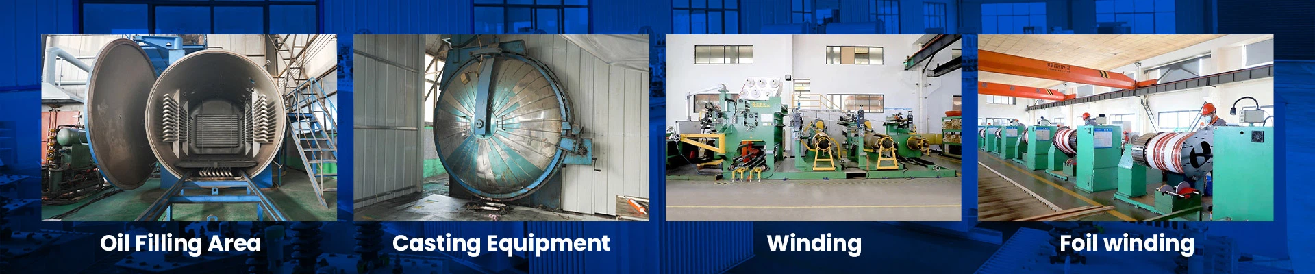
With years of industry experience, GNEE Electric specializes in the R&D and production of oil-immersed power transformers. Leveraging our technical expertise and rigorous quality control, we provide customized solutions. First, understand the essentials, then select the right equipment-keep reading for all the practical insights!
Basic Structure of a Transformer: Seven Essential Components, None of Which Can Be Omitted
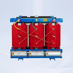
Large oil-immersed power transformers feature a complex and precise structure. Their basic composition consists of seven core components, which work in concert to ensure stable and efficient operation. The first two components are the fundamental core parts, responsible for the core function of energy conversion.

Core Assembly: Composed of columns and yokes made of laminated silicon steel sheets, along with their clamping mechanisms, this forms the magnetic circuit core of the transformer and serves as the medium for energy transfer.
Winding Assembly: This includes the windings for each phase and their connecting leads. As the electrical circuit core of the transformer, it constitutes the electrical circuit for inputting and outputting electrical energy.
Insulation System: This encompasses the oil and paper insulation between components as well as within the transformer itself. Its primary function is to isolate live parts, prevent short circuits, ensure operational safety, and extend the equipment's service life.
Tank System: In addition to the tank body, this includes the oil reservoir and supports. It serves as the primary container for housing the core and transformer oil, while also protecting internal components and aiding in heat dissipation.
Cooling System: Composed of coolers or radiators, oil pumps, fans, and connecting pipes, its core function is to dissipate heat generated during transformer operation, preventing equipment damage due to overheating.
Measuring Instruments: Including signal thermometers, current transformers, and oil level gauges, these are used to monitor the transformer's operating status in real time and promptly provide feedback on critical data such as temperature, current, and oil level.
Protective Devices: These include pressure relief devices, gas relays, and moisture absorbers. They serve as the transformer's "safety line of defense," triggering protective mechanisms promptly when abnormalities occur to prevent the escalation of faults.

Among these, the core and windings are referred to as the magnetic circuit and electrical circuit, respectively. They form the core foundation for the transformer's energy conversion, and their coordinated operation is a prerequisite for the transformer's normal functioning.
Transformer Core: The "Magnetic Path Bridge" for Energy Conversion
The core is the fundamental component of a transformer, consisting of magnetic conductors and clamping devices. It serves both functional and structural purposes and acts as the key medium for energy conversion in a transformer.
From a functional perspective, the magnetic conductors of the core form the core of the transformer's magnetic circuit, responsible for converting electrical energy from the primary circuit into magnetic energy, and then converting that magnetic energy back into electrical energy for the secondary circuit, thereby completing the transmission and conversion of electrical energy.
Structurally, the core supports all internal components of the transformer, such as the body and leads, serving as the "skeleton" of the entire device.
The transformer core adopts a box-shaped closed structure, in which the portion wrapped with windings is called the core columns, while the portion not wrapped with windings and serving only to close the magnetic circuit is called the core yoke. Its labeled components mainly include: upper clamping piece, main columns, tie plates, lower clamping piece, upper core yoke, and lower core yoke.

Types of Cores
Based on the relative positions of the windings and the core, cores can be broadly classified into two types: core-type and shell-type. Among these, the core-type core is most widely used in oil-immersed power transformers; this section focuses on the structural forms of core-type cores.
- For single-phase transformers, the core primarily comes in several structural forms, such as two columns and two yokes, one column and four yokes, and two columns and four yokes, to accommodate different single-phase power supply requirements.
- For three-phase transformers, core configurations include two-column-two-yoke (three-phase, three-column) and three-column-four-yoke (three-phase, five-column), primarily used for power conversion in three-phase power systems.

The selection of core configurations requires a comprehensive consideration of various factors, including the rationality of winding arrangement, material efficiency, and transportation height restrictions, to ensure that the transformer meets operational requirements while achieving a balance between cost-effectiveness and practicality. Related components include: yoke, column side yoke, and lower core yoke.
Transformer Windings: The "Core Circuit" for Electrical Power Input and Output
The windings constitute the electrical circuit through which a transformer inputs and outputs electrical power; they are also one of the transformer's core components. Made of flat copper (or aluminum) conductors and equipped with various insulating components, the quality of their design directly determines the transformer's operational stability and service life. In terms of design, the windings must meet three fundamental requirements-electrical strength, thermal strength, and mechanical strength-all of which are indispensable.

1. Electrical Strength Requirements
The windings must possess sufficient electrical strength to withstand various voltage surges, primarily including lightning impulse withstand voltage, switching impulse withstand voltage, and power frequency withstand voltage. This prevents insulation damage caused by voltage surges, which could lead to short-circuit faults.
2. Thermal Strength Requirements
Under the thermal effects generated by long-term operating currents, the service life of the coil insulation should be no less than 20 years. Additionally, during transformer operation, if a sudden short circuit occurs at any terminal, the coil must be able to withstand the thermal effects of the short-circuit current without damage, ensuring the safety of the equipment under extreme conditions.
3. Mechanical Strength Requirements
The coil must possess sufficient mechanical strength to withstand electromagnetic forces, vibrations, and other stresses generated during operation, preventing deformation or damage to the coil, safeguarding the integrity of the circuit, and ensuring the normal input and output of electrical energy.

Coil Structure Markings and Winding Configuration Notes
The structural markings of the coil primarily include: cooling oil channels, guide partitions, spacers, and winding configuration.
Among these, phase shifting is a critical process in coil design, as explained below: When the transformer current is high, the coil turns consist of multiple parallel conductors. To ensure uniform current distribution among the parallel conductors-that is, to ensure equal conductor lengths and equal magnetic flux links with the leakage magnetic field-the positions of the parallel conductors must be swapped. This operation, referred to as "phase shifting," is a crucial process for ensuring normal coil operation and preventing local overheating.
Transformer Core: An "Integrated Assembly" of Core Components
The transformer core is formed by assembling the iron core and coils of various voltage levels, securing them with clamping devices, and welding on the leads. Simply put, the transformer core serves as an integrated carrier for core components such as the iron core and coils. It generally consists of two parts: the iron core clamping assembly and the coil clamping assembly, and functions as the core assembly responsible for energy conversion within the transformer.

Its labeled components primarily include: terminal plates, windings, leads, the core, clamping plates, on-load tap changers, conductor clamps, and support plates. These components work in concert to ensure the structural stability of the core and efficient electrical energy conversion.
Transformer Tank: The Equipment's "Protective Housing" and "Oil Reservoir"
The transformer tank is the core container that houses the core assembly and transformer oil. It simultaneously serves multiple functions, including heat dissipation, insulation protection, insulation drying, providing a base, and facilitating transportation. It is an indispensable and vital component of the transformer, and its performance directly affects the transformer's operational stability and service life.

Core Functions of the Tank
- Oil Storage: Stores transformer oil, providing a medium for insulation and heat dissipation;
- Heat Dissipation: Works in conjunction with the cooling system to dissipate heat generated during transformer operation;
- Insulation Protection: Isolates insulation components from the atmosphere, preventing the absorption of moisture and gases, and inhibiting the aging of transformer oil;
- Insulation Drying: Acts as a "vacuum tank" during vacuum extraction at ambient temperatures on-site;
- Base: Provides stable support for the entire transformer;
- Transportation: Facilitates the overall handling and installation of the transformer.

Types of Oil Tanks
There are two basic types of transformer oil tanks: barrel-type tanks and bell-type tanks. These two types have opposite advantages and disadvantages and are suitable for different application scenarios.
- Barrel-type tanks: Consist of a tank cover and a barrel body. Their advantage is a simple appearance, and only a small amount of transformer oil needs to be drained when lifting the tank; The disadvantage is that for large-capacity transformers, on-site maintenance requires a crane with sufficient lifting capacity; therefore, it is suitable for small- and medium-capacity transformers.
- Bell-shaped Tank: Consisting of an upper and lower section, its advantages and disadvantages are the opposite of those of the barrel-type tank. The advantage is that large-capacity transformers can be maintained without a large crane; the disadvantage is that a large amount of transformer oil must be drained when lifting the tank body, and its appearance is relatively complex. It is suitable for large-capacity transformers.
Tank Accessories
Tank accessories are essential components that ensure the proper operation of the tank.
The main components include: riser, base plate, reinforcing plate, base frame, jack bracket, oil reservoir, oil reservoir bracket, lifting eye, and cooling system pipe fittings. Each accessory serves a specific function to ensure the tank's sealing performance, stability, and functionality.
Transformer Components
Tap Changer: The "Core Component" of Voltage Regulation
In the operation of power systems, voltage regulation of transformers is necessary to supply stable voltage, control power flow, or regulate load current. Currently, the core method for adjusting transformer voltage involves installing taps on one of the windings. By removing or adding a portion of the windings to change the number of turns, a stepped adjustment of the voltage ratio is achieved. The component that performs this function is the tap changer.
Typically, taps are installed on the high-voltage winding for two main reasons: First, the high-voltage winding is usually located on the outside, making it more convenient to bring out the tap leads; second, the current on the high-voltage side is relatively low, allowing for smaller cross-sections in the tap leads and current-carrying parts of the tap changer, which reduces manufacturing complexity and lowers costs.

Based on the transformer's operating state during voltage regulation, voltage adjustment can be divided into two types: voltage regulation performed when the secondary winding is unloaded and the primary winding is disconnected from the grid (voltage regulation without power supply) is called de-energized (no-load) voltage regulation; voltage regulation performed while the transformer is under load by changing the tap position of the winding is called on-load voltage regulation. Therefore, transformer tap changers are also divided into two categories: no-load tap changers and on-load tap changers (illustration labels: on-load tap changer, no-load tap changer).
Transformer Components-On-Load Tap Changer
The on-load tap changer is one of the key core components of a transformer. Its primary function is to switch tap positions while the transformer is under load and without interrupting power supply, thereby altering the transformer's voltage ratio to precisely regulate the output voltage. This addresses voltage instability issues in power systems caused by load fluctuations and grid voltage deviations, ensuring the normal operation of electrical equipment. It is widely used in scenarios requiring continuous and stable power supply.

Compared to de-energized tap changers, the greatest advantage of on-load tap changers is "voltage regulation without power interruption." They allow voltage adjustment to be completed without interrupting the power supply, thereby avoiding production downtime and inconvenience to users caused by power outages during voltage adjustment. They are particularly suitable for scenarios with extremely high requirements for power supply continuity, such as the main grid of power systems, large-scale industrial production lines, and power distribution networks in high-rise buildings.
Its core operation relies on the coordinated action of the "transition circuit" and the "switching mechanism." During tap switching, this ensures the continuous flow of load current, preventing arcing and voltage sags, thereby protecting transformer windings and grid equipment from damage.

On-load tap changers have stricter operational requirements and must possess excellent insulation performance, current-carrying capacity, and arc-quenching capabilities. Regular maintenance and inspections are also necessary, including checks on the quality of insulating oil, the flexibility of the switching mechanism, and the integrity of the transition resistors, to prevent transformer damage or power outages caused by switch failures. In addition, the voltage regulation range of on-load tap changers is typically broader than that of no-load tap changers, generally allowing for voltage adjustment within a range of ±10% or greater, enabling better adaptation to fluctuations in grid voltage.
Transformer Components-De-energized Tap Changer
The core function of a de-energized tap changer is to change the transformer's tap position without applying voltage to the transformer, thereby altering the voltage ratio. It is suitable for scenarios where voltage regulation does not require the transformer to be under load.

Voltage-regulating tap changers can be classified into single-phase and three-phase types based on the number of phases; based on the location of voltage regulation, they can be divided into three types: neutral-point voltage regulation, mid-point voltage regulation, and line-end voltage regulation (illustration caption: drum-type switch).
Their structure is relatively simple, consisting primarily of tap positions, switching components, and an operating mechanism. They do not require complex components such as shunt resistors, resulting in lower manufacturing costs and easier maintenance. Since power must be shut off during voltage adjustment, these switches are primarily used in applications where continuous power supply is not critical, such as rural distribution networks, small industrial transformers, and distribution transformers in residential buildings.
They are typically employed in environments with minimal grid voltage fluctuations and gradual load changes, where voltage is precisely calibrated by switching tap positions during scheduled power outages.
Oil Reservoir: The "Regulation and Protection Hub" for Transformer Oil
The oil reservoir serves as the oil protection system for oil-immersed transformers and on-load tap changers, and its core function is closely tied to changes in the volume of transformer oil. Fluctuations in ambient temperature and variations in transformer load can cause changes in the temperature of the oil inside the transformer tank; simultaneously, changes in ambient temperature and switching operations of the on-load tap changer can also cause temperature fluctuations in the transformer oil within the on-load tap changer's oil compartment.
These temperature changes inevitably lead to the contraction and expansion of the transformer oil's volume.
The core mission of the oil reservoir is to regulate the volume changes of the transformer oil in both the transformer tank and the on-load tap changer's oil compartment, while preventing moisture ingress and the oxidative effects of air on the transformer oil, thereby ensuring the transformer oil's insulation performance and service life.

Classification of Oil Reservoirs
Oil reservoirs are primarily divided into open-type and sealed-type varieties. Sealed-type oil reservoirs are more widely used and can be further classified into capsule-type, diaphragm-type, and metal bellows-type, catering to the specific requirements of different applications.

Structure of Capsule-Type Oil Reservoirs
The capsule-type oil conservator is a common type of sealed oil conservator. It primarily consists of a cabinet, a capsule, a gas collection chamber (equipped with components such as the main tank piping, oil filling and draining lines, vent lines, contaminated oil discharge lines, and small-tube oil gauges), a desiccant and associated piping, a vent plug, a drain plug, and an oil level gauge (as indicated in the schematic diagram: vent plug). These components work together to provide effective protection for the transformer oil and regulate its volume.
Cooling System: The "Heat Dissipation Safeguard" for Equipment
During operation, transformers generate a significant amount of heat due to losses. If this heat cannot be dissipated in a timely manner, it can cause the equipment to overheat, damaging insulation components, shortening service life, and even leading to safety failures. Therefore, the cooling system serves as the "heat dissipation safeguard" for transformers; its core function is to dissipate the heat generated by losses during operation, ensuring the transformer operates stably within a safe temperature range.

For 110kV power transformers, there are two primary cooling methods: natural cooling and forced air cooling. Natural cooling relies on the natural convection of transformer oil to dissipate heat; it features a simple structure and is easy to maintain, making it suitable for applications with lighter loads and lower heat generation. Forced air cooling, on the other hand, uses fans to assist in heat dissipation, offering higher cooling efficiency. It is suitable for applications with heavier loads and higher heat generation, better meeting the equipment's cooling requirements.
Pressure Relief Valve: The Equipment's "Safety Pressure Relief Device"
The transformer pressure relief valve is a spring-loaded valve and serves as one of the core safety protection devices for transformers, primarily designed to address situations where internal pressure rises abnormally. When the internal pressure of the transformer exceeds the spring's opening force, the actuator disc moves slightly upward.
At this point, the internal pressure immediately spreads across the side-sealed surface of the actuator disc, causing it to open abruptly and rapidly release the internal pressure. Once the pressure drops to a safe range, the spring pulls the actuator disc back to the sealed position, completing the pressure relief protection.
The pressure relief valve can be equipped with an alarm switch and requires manual reset after activation. It also features a mechanical indicator rod that visually confirms whether the valve has actuated (see illustration: mechanical indicator rod, spring).

Transformer Components-Pressure Relief Cylinder
The transformer pressure relief cylinder is an early type of pressure relief device for transformers. Its structure is relatively simple: a pressure relief plate (typically flat glass) is installed in the middle of the cylinder, with a mesh guard below to prevent glass fragments from falling into the transformer interior if the glass breaks.

Currently, this type of pressure relief cylinder has been phased out, though it is still used in some older transformers; however, its protective performance and reliability are far inferior to those of modern pressure relief valves.
Conclusion
This article comprehensively covers the core knowledge of oil-immersed power transformers, ranging from basic composition to key components, and from structural characteristics to functional roles. It aims to help industry professionals and power enthusiasts fully grasp the core knowledge of oil-immersed power transformers and understand their vital role in power systems.
With the upgrading of power systems and the rapid development of new energy sources, oil-immersed power transformers are evolving toward greener and smarter technologies, continuing to provide core support for the stability and efficiency of power transmission.
Once you understand the core principles of oil-immersed power transformers, you'll realize just how important it is to choose the right equipment!
Leveraging years of industry experience, GNEE Electric strictly controls the production and assembly of every core component-from the core and windings to the cooling system and protective devices-all in accordance with the highest industry standards.
We can customize oil-immersed power transformers tailored to your specific applications (power grids, industrial power, renewable energy plants, etc.), balancing stability, durability, and cost-effectiveness.
We provide comprehensive technical support and after-sales service throughout the entire process, so you never have to worry about equipment quality or maintenance.
Contact GNEE Electric today to select a reliable oil-immersed power transformer that will safeguard your power transmission!
Send Inquiry