







How to Design a 100kVA Dry-Type Transformer Power Distribution Project: A Step-by-Step Guide
Feb 04, 2026
Leave a message
At GNEE, we are more than a manufacturer; we are a technical partner for your power distribution projects. Designing a system around a 100kVA dry-type transformer requires careful planning to ensure safety, reliability, and compliance.
This guide provides a structured, 6-step framework to help engineers and project planners create an optimized and robust design, integrating key considerations and highlighting how GNEE supports each stage.
Step 1: Define Requirements and Load Analysis
Core Activity: Precisely determine the electrical demand and environmental conditions.
Key Actions:
- Load Profiling: Calculate the total connected load (kVA) and the maximum diversified demand. Identify load types (motors, lighting, sensitive electronics) to account for inrush currents and harmonics.
- Voltage Levels: Confirm the available supply voltage (e.g., 11kV, 20kV) and required secondary distribution voltage (e.g., 400V/230V).
- Location & Environment: Determine indoor/outdoor installation, ambient temperature, humidity, altitude, and exposure to dust or corrosive substances. This dictates the transformer's enclosure IP rating (e.g., IP23 for outdoor) and insulation class.
GNEE Support: We assist in reviewing load calculations and recommending the optimal dry-type transformer specifications, including special coatings for harsh environments.
Step 2: Select and Specify the Transformer
Core Activity: Translating requirements into detailed technical specifications.
Key Specifications to Define:
- Rating: 100kVA, with explicit primary and secondary voltages.
- Impedance Voltage (%Z): Typically 4% or 6% for 100kVA. Select based on required fault current limitation and system coordination.
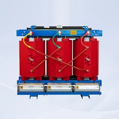
- Insulation Class: Class F (155°C) or Class H (180°C) for thermal longevity.
- Protection Level: IP20 for clean indoor rooms, IP23 for outdoor/ducted ventilation, IP54 for dusty/damp areas.
- Accessories: Specify temperature controllers (PT100 sensors, alarm/trip contacts), protective covers, and cooling fans (AN/AF).
GNEE Support: We provide detailed datasheets and custom dry-type transformer solutions tailored to your exact specification sheet.
Step 3: Design the Protection and Coordination Scheme
Core Activity: Protecting the transformer and downstream circuits from faults.
Protection Elements:
- Primary Side (HV): Select appropriate fuses or a circuit breaker to protect against internal faults and severe overloads.
- Transformer Internal: Rely on the built-in temperature control system (from Step 2) for overload and winding temperature protection.
- Secondary Side (LV): Design the main low-voltage circuit breaker with the right trip settings (thermal-magnetic or electronic) to protect the secondary cables.
- Coordination: Ensure the protective devices are selectively coordinated so only the faulty circuit is disconnected.
GNEE Support: Our technical documents provide essential data (fault current withstand, thermal curves) for accurate protective device setting calculations.
Step 4: Plan Physical Layout and Installation
Core Activity: Ensuring proper mechanical and thermal installation.
Critical Considerations:
- Clearances: Maintain minimum safe distances from walls and other equipment as per IEC standards for cooling airflow and maintenance access.
- Ventilation: Design adequate room ventilation or specify transformer enclosure ducting to dissipate heat losses. Calculate required airflow.
- Foundations & Mounting: Provide a level, solid base capable of supporting the transformer's weight and vibration.
- Cable Connections: Plan for proper cable entry, bending radii, and termination space for both HV and LV sides.
GNEE Support: We offer detailed dimensional drawings, weight details, and installation manuals to inform your layout design.
Step 5: Integrate with Distribution Equipment
Core Activity: Connecting the transformer to the complete switchgear system.
Downstream Components:
- LV Switchboard: The transformer feeds into the main LV distribution board (MDB).
- Sub-Distribution Boards (SDBs) and Final Circuits: Plan the distribution paths from the MDB.
- Power Factor Correction (PFC): Design capacitor banks, often installed at the LV busbar, to improve efficiency and reduce penalties.
- Earthing/Grounding System: Design a compliant system for transformer neutral and enclosure grounding.
GNEE Support: Our transformers are designed for seamless integration with standard power distribution equipment.
Step 6: Commissioning and Compliance
Core Activity: Testing the system to ensure design integrity.
Key Procedures:
- Pre-energization Checks: Verify insulation resistance, tightness of connections, and protection settings.
- Energization & Load Testing: Apply voltage in stages and monitor inrush current, temperature rise, and noise levels under increasing load.
- Documentation: Ensure all electrical diagrams, test reports, and transformer manuals (like our GNEE dry-type transformer manual) are compiled for the end-user.
- Compliance: Confirm adherence to all relevant local and international standards (IEC, IEEE, etc.).
GNEE Support: We provide commissioning checklists and are available for technical consultation during the critical startup phase.
Design Summary: Key Technical Parameters Table
| Design Phase | Key Parameter | Typical Consideration for 100kVA Project |
|---|---|---|
| Step 1: Requirements | Total Demand Load | Must be ≤ 100kVA, with consideration for future expansion. |
| Step 2: Transformer Spec | Impedance (%Z) | 4% or 6%. Affects voltage regulation and short-circuit current. |
| Step 3: Protection | Primary Protection | HV Fuse (e.g., 25A) or Circuit Breaker with appropriate breaking capacity. |
| Step 4: Installation | Clearance (Front) | Minimum 600mm for maintenance and cooling airflow. |
| Step 5: Integration | LV Breaker Rating | Main LV ACB/MCCB typically rated 160A-200A, with adjustable trip settings. |
| Step 6: Commissioning | Insulation Resistance | > 1000 MΩ (HV-LV, HV-Earth, LV-Earth) at 25°C as per IEEE 43. |
Conclusion: From Design to Reliable Operation
Successfully designing a 100kVA dry-type transformer power distribution project is a systematic process that balances electrical requirements, safety standards, and practical installation constraints. By following these steps, you ensure a system that is safe, efficient, and compliant.
GNEE stands ready to support you from the initial specification through to commissioning, providing not only the core 100kVA dry-type transformer but also the critical technical expertise for a seamless project execution.
Ready to begin your project design?
Contact the GNEE engineering team today for detailed specifications, technical drawings, and a collaborative design review. Request a project consultation now.
Send Inquiry