


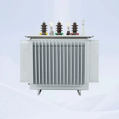





Loss Analysis and Energy Efficiency Comparison of 750 kVA Oil Filled Transformer
Mar 25, 2026
Leave a message
For a 750 kVA oil-filled transformer the whole efficiency story fits in two numbers: no-load loss and load loss. Using the GB 20052-2020 limits for 10 kV oil-immersed units (linear-interpolated to 750 kVA), a level-3 unit sits near 660 W no-load / 7,100 W load, while a level-2 unit drops to about 600 W / 6,100 W - roughly 1,080 kWh less annual energy for the level-2 choice, before capitalising the difference over a 20-year service life.
Key Takeaways
- Two loss components: no-load (core) loss is constant once energised; load (copper) loss grows with the square of the load current. Total loss = P0 + Pk × (load factor)².
- Benchmarks: for 750 kVA (interpolated, GB 20052-2020, Dyn11): level 3 ≈ 660/7,100 W; level 2 ≈ 600/6,100 W; level 1 ≈ 540/5,100 W (no-load/load).
- Verified math: cutting total loss by 500 W saves 4,380 kWh per year (500 W × 8,760 h) - the basis of the TOC payback calculation.
- Peak efficiency: occurs at β = √(P0/Pk) ≈ 30% of rating for a typical unit; the economical operating band is usually 40–60%.
At GNEE, we utilize advanced core-stacking technologies and high-purity electrolytic copper to ensure every 750 kVA oil filled transformer we produce meets and exceeds international efficiency standards, providing a reliable backbone for your power grid.
Defining the Two Loss Components
1.1 No-load loss (core loss)
No-load loss appears the moment the transformer is energised, whether or not it feeds a load. It is the energy consumed by the magnetising of the core: hysteresis loss in the silicon steel and eddy current loss induced in the laminations. The material choice dominates this number - grain-oriented silicon steel (CRGO) with thin, well-insulated laminations keeps both components low. Because no-load loss runs 24/7, it is often the larger item in a 20-year cost model even though it is numerically smaller than load loss.
1.2 Load loss (copper loss)
Load loss is dissipated in the windings when current flows - fundamentally the I²R loss of the conductors, plus stray losses in structural parts. It scales with the square of the load factor: at 50% load only 25% of the rated load loss appears. Copper windings with properly designed cross-sections and low-resistance terminations keep this component in check.
Total loss = P0 + Pk × β², where P0 = no-load loss, Pk = load loss at rated current, β = load factor. Every procurement decision on a distribution transformer starts from this equation.

High-quality CRGO silicon steel core and copper winding assembly of a 750 kVA oil filled transformer inside the factory
2. Efficiency Benchmarks: GB 20052-2020 for 750 kVA
GB 20052-2020 sets three efficiency levels for 10 kV oil-immersed distribution transformers (30–2500 kVA). 750 kVA is not a listed row, so the limits are obtained by linear interpolation between 630 kVA and 800 kVA (Dyn11 group, grain-oriented core):
| Efficiency Level | No-Load Loss (W) | Load Loss (W) | Full-Load Efficiency* |
|---|---|---|---|
| Level 3 (mandatory limit) | ≈ 660 | ≈ 7,100 | ≈ 98.97% |
| Level 2 (high efficiency) | ≈ 600 | ≈ 6,100 | ≈ 99.11% |
| Level 1 (premium) | ≈ 540 | ≈ 5,100 | ≈ 99.25% |
*Efficiency = S / (S + P0 + Pk) at rated load, 750 kVA. Values are linear interpolations of GB 20052-2020 Table 1 (Dyn11 group) and are indicative; the binding numbers are those on the manufacturer's type-test report.
Practical consequence: a level-2 unit beats a level-3 unit by roughly (660−600) + (7,100−6,100) = 1,060 W of loss headroom at full load - about 9,286 kWh/year at full-load continuous operation, and proportionally less at typical average loading. Either way, the energy saving is real, recurring, and capitalisable.
3. Technical Parameters at a Glance
| Parameter | Standard-Efficiency Unit (≈ Level 3) | High-Efficiency Unit (≈ Level 2) |
|---|---|---|
| Rated capacity | 750 kVA | 750 kVA |
| Cooling method | ONAN | ONAN / ONAF |
| No-load loss | ≤ ~700 W | ≤ ~620 W |
| Load loss (75 °C) | ≤ ~7,200 W | ≤ ~6,300 W |
| Short-circuit impedance | 4.0% – 6.0% | 4.0% – 5.0% |
| Insulation level | LI 75 AC 28 | LI 75 AC 28 (standard) / enhanced |
| Oil type | Mineral oil | Mineral oil or natural ester |
Table for 10 kV class (Um = 12 kV), vector group Dyn11/Yyn0. LI 75 AC 28 = lightning impulse withstand 75 kV peak, power-frequency withstand 28 kV, per IEC 60076-3 / GB/T 1094.3. Confirm final figures with the factory test report.

750 kVA oil-filled transformer undergoing final testing
4. Total Ownership Cost (TOC) and the 4,380 kWh Example
The capitalized cost of losses (TOC) is the honest way to compare transformers:
TOC = purchase price + A × P0 + B × Pk, where A and B are the capitalised values of 1 W of no-load and load loss over the service life (typically 20 years), set by your energy tariff, load factor and discount rate.
Worked example with the rule of thumb used above: a 500 W reduction in total loss saves 500 W × 8,760 h = 4,380 kWh per year. At, say, $0.12/kWh that is ≈ $526/year of recurring saving. Capitalised over 20 years (before discounting) it reaches ≈ $10,500 - versus a one-time efficiency premium that is usually a fraction of that. Whether the payback lands at 2–3 years depends on your tariff and load factor, but the direction of the economics is not in doubt.
5. Manufacturing and Installation Factors That Protect the Loss Values
5.1 Factory practices that keep losses at nameplate
- Vacuum drying and oil filling: removing residual moisture from the insulation before filling under vacuum prevents bubbles and keeps dielectric strength at design level.
- Precision winding: tight, uniform coils improve short-circuit strength and keep stray losses low.
- Surface protection: shot-blasted tanks with durable paint resist coastal salt and industrial pollutants, protecting cooling efficiency over time.
5.2 Site practices that stop losses from creeping up
- Ventilation: keep radiator fins clear - roughly 1 m clearance for natural convection cooling.
- Oil quality: sample and test dielectric strength periodically; degraded or contaminated oil reduces insulation margin and heat transfer, raising operating temperature.
- Terminations: loose connections add resistance and heat; torque-check bushings and busbar joints on schedule.
Conclusion: Optimize Your Grid with GNEE 750 kVA Oil Filled Transformers
Selecting the right equipment requires a deep dive into loss analysis and energy performance. A high-quality 750 kVA oil filled transformer is more than just a piece of hardware; it is a critical component that ensures the safety, efficiency, and profitability of your operations. By choosing GNEE as your manufacturer, you gain access to world-class engineering, transparent loss data, and a commitment to energy excellence.
Ready to reduce your energy costs?
Whether you need a standard unit or a custom-engineered solution, our team is here to help. [Contact GNEE today for a detailed Loss Analysis Report and a Competitive Quote on our 750 kVA oil filled transformers!]
References
- GB 20052-2020 - (Minimum allowable values of energy efficiency and the energy efficiency grades for power transformers).
- GB/T 6451-2023 - Technical parameters and requirements for oil-immersed power transformers).
- IEC 60076-1 - Power transformers, Part 1: General.
- IEC 60076-7 - Power transformers, Part 7: Loading guide for oil-immersed power transformers.
- GNEE Electric - Oil-Immersed Transformer range.
- Standards and figures above were verified against the cited sources as of the publication date. Loss values interpolated from GB 20052-2020 Table 1 are indicative; the manufacturer's type-test report is the binding reference. If you spot an error, contact us so we can correct it.
Send Inquiry