








Why a 10kV Transformer Should NOT Have a Lightning Rod on Its Frame
May 26, 2026
Leave a message
Putting a lightning rod on a 10kV transformer frame is not protection - it is the opposite. The rod turns the transformer into a preferred strike target, and the resulting ground potential rise can arc back through the tank into the windings. Distribution transformers are protected by metal oxide arresters (MOA) mounted on the line near the terminals, with a three-in-one common earthing system, never by an air rod bolted to the unit.
Key Takeaways
- Why not: a rod on the frame attracts the strike to the transformer; up to ~200 kA (10/350 µs, IEC 62305) flows into the local ground, raising ground potential and causing backflashover through the windings.
- Correct device: a metal oxide arrester (MOA) mounted on the line as close as possible to the transformer terminals clamps the incoming surge without attracting strikes.
- Mandatory earthing: the three-in-one method - arrester down conductor, transformer tank and LV neutral share one earthing system; independent arrester earthing is prohibited.
- Grounding limits: ≤ 10 Ω for 100 kVA and below, ≤ 4 Ω above 100 kVA (per DL/T 620-type practice; confirm with the local utility code).
1. The "Attraction Effect" That Backfires
A lightning rod works by deliberately attracting the discharge to itself, intercepting the strike and routing the current down a dedicated conductor to ground. For a building or a substation yard, that is exactly what you want: the rod takes the hit so the structure does not.

On a transformer gantry the geometry inverts. The rod sits metres from a machine full of insulation that cannot survive a direct hit, and the lightning current - which can reach peak values in the order of 200 kA (first positive stroke, 10/350 µs waveform, per IEC 62305-1) - is dumped into the ground directly beside the transformer. If the earthing system cannot absorb that impulse instantly, the ground potential rises sharply. That is ground potential rise (GPR), and its companion is backflashover: the elevated potential arcs from the earthing system back through the tank and into the windings, bypassing every intended discharge path and punching through the insulation. The transformer fails even though it was never directly struck.
Rule to remember: an air termination protects structures; a surge arrester protects equipment connected to lines. A distribution transformer is line-connected equipment, so it needs the arrester - not a rod on its own frame.
2. The Correct Core: Metal Oxide Arresters (MOA)
A zinc-oxide arrester has a highly non-linear volt-ampere characteristic. At normal operating voltage it is effectively an insulator; when a lightning-induced overvoltage appears, its resistance collapses and it shunts the surge current to ground, clamping the voltage across the protected insulation to a safe level.
Placement matters more than the device itself:
- Location: as close as possible to the transformer terminals, ideally directly at the HV bushings and between the transformer and the HV fuse. The shorter the unprotected lead, the lower the overvoltage that reaches the windings.
- Lead conductor: for MOA with rated voltage up to 42 kV, the connection lead should be multi-strand flexible copper with a cross-section of not less than 16 mm², run as short and straight as possible to minimise inductance.
- Mounting: vertical on a stable base, with a cushion between the porcelain sleeve and the fixing hoop to avoid mechanical stress, and tightly connected leads.
- Phase spacing: for 1–10 kV arresters, phase-to-phase distance not less than 350 mm to prevent phase-to-phase flashover.
3. The "Three-in-One" Grounding Principle
An arrester is only as good as its earth path. The three-in-one method is mandatory in distribution practice: the arrester grounding down conductor, the transformer metal tank, and the low-voltage neutral point must all be bonded into one common earthing system.
Independent earthing of the arrester is prohibited: if the arrester had its own isolated earth, lightning current would be forced to flow through the transformer body to reach the main ground, generating a destructive voltage difference across the insulation - precisely the failure the arrester exists to prevent.
Grounding Resistance: The Foundation
| Transformer Capacity | Maximum Grounding Resistance |
|---|---|
| 100 kVA and below | ≤ 10 Ω |
| Above 100 kVA | ≤ 4 Ω |
Typical limits per distribution grounding practice (e.g. DL/T 620). Always confirm with the project specification and the local utility's earthing code, which may impose lower values in high soil-resistivity or sensitive areas.
Measure the earth resistance after installation and re-verify it periodically: a corroded joint or dried-out earth electrode quietly turns an otherwise correct scheme into a hazard.
A Complete 10kV Lightning Protection Package

- MOA selection matched to the system voltage and insulation level (e.g. 17 kV rated arrester for 10 kV systems, per IEC 60099-4 class selection).
- Arrester mounted at the HV terminals with ≤ 16 mm² flexible copper leads, ≤ 350 mm phase spacing.
- Three-in-one common earthing: arrester down conductor + tank + LV neutral.
- Grounding resistance verified ≤ 4 Ω (transformers above 100 kVA) with a clamp or fall-of-potential test.
- For exposed yards, a separate air-termination and earth grid at a safe distance protects the station - the arrester protects the transformer.
Need to source reliable 10kV transformers with proper lightning protection configurations for your project?
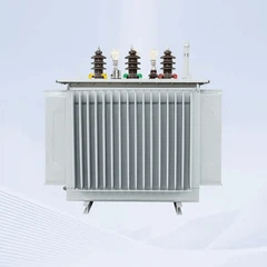
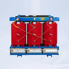
At GNEE, we not only supply high-quality oil-immersed and dry-type transformers, but we also provide complete technical documentation-including lightning protection schematics, arrester selection guides, and grounding layout recommendations-to help you meet international standards and keep your installation safe.
Contact our engineering team today to discuss your requirements or request a quote. We're here to help you get the right solution for your power distribution needs.
FAQ
Why can't a lightning rod be installed on a 10kV transformer frame?
A lightning rod deliberately attracts strikes to itself. Installed on the transformer frame it turns the transformer into the strike target, and the huge impulse current (up to ~200 kA per IEC 62305) raises the local ground potential. The resulting voltage can arc back from the grounding system through the tank and windings - a backflashover - destroying the insulation. Transformers are protected by surge arresters on the line, not by rods on the frame.
What is the difference between a lightning rod and a lightning arrester (MOA)?
A lightning rod (air termination) is a physical structure that intercepts a direct strike and routes the current to ground through a down conductor - it protects buildings and substation yards. A metal oxide arrester (MOA) is a non-linear device installed on the power line near the transformer terminals; it does not attract lightning but clamps overvoltages arriving along the line by shunting surge current to ground, protecting insulation.
What grounding resistance is required for a 10kV distribution transformer?
Per common distribution practice (e.g. DL/T 620 and Chinese grid codes), the grounding resistance of the transformer neutral and tank earthing should be ≤ 10 Ω for transformers rated 100 kVA and below, and ≤ 4 Ω above 100 kVA. The final limit must always follow the local utility code and the project specification.
What is the three-in-one grounding method?
The three-in-one method connects the arrester grounding down conductor, the transformer metal tank, and the low-voltage neutral point to one common earthing system. Independent earthing of the arrester is prohibited because lightning current would then be forced to flow through the transformer to reach the main ground, creating a destructive potential difference across the insulation.
References
- IEC 62305-1 - Protection against lightning, Part 1: General principles (lightning current parameters, 10/350 µs waveform).
- IEC 60099-4 - Surge arresters, Part 4: Metal-oxide surge arresters without gaps for a.c. systems.
- DL/T 620-2019 - (Overvoltage protection and insulation coordination for AC electrical installations).
- GB 50057-2010 - (Code for design protection of structures against lightning).
- GNEE Electric - Distribution Transformer range.
Standards and figures above were verified against the cited sources as of the publication date. If you spot an error, contact us so we can correct it.
Need a 10kV Transformer with a Compliant Lightning Protection Scheme?
GNEE supplies oil-immersed and dry-type distribution transformers with arrester selection guides, earthing layouts and full technical documentation to meet international standards.
Or email :sales@gneeelectric.com
WhatsApp: +86 158 2468 7445
Send Inquiry