


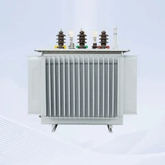
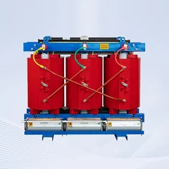






How to Control Oil Leakage & Pressure in 1500kVA Oil Filled Transformer Tank?
Oil leakage and uncontrolled pressure are the two most common causes of premature failure in liquid-filled power equipment. If you do not know how to control oil leakage & pressure in a 1500kVA Oil Filled Transformer tank, your investment is at risk of environmental fines, unplanned downtime, and even catastrophic tank rupture.
As an ISO9001:2015 certified manufacturer with over 18 years of experience and a 30,000㎡ smart factory, GNEE has engineered thousands of tanks that remain leak-free for 25+ years. In this comprehensive guide, we reveal proven methods-from robotic welding to pressure relief devices-that ensure your 1500kVA Oil Filled Transformer operates safely under all conditions.

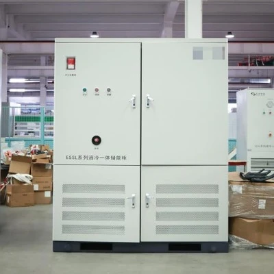
GNEE factory warehouse with 1500kVA Oil Filled Transformer tanks ready for shipment
Why Oil Leakage & Pressure Control is Critical for a 1500kVA Oil Filled Transformer Tank
Understanding how to control oil leakage & pressure in a 1500kVA Oil Filled Transformer tank begins with recognizing the consequences of failure. The tank is not a passive container-it is a dynamic pressure vessel subject to thermal expansion, vibration, and dielectric stress.
The High Cost of Oil Leakage
Even a pinhole-sized leak in a 1500kVA Oil Filled Transformer tank leads to:
- Dielectric breakdown: Oil level drops, exposing windings to air and moisture, which reduces insulation strength from >40 kV/mm to <10 kV/mm.
- Environmental penalties: Oil spills trigger regulatory fines (EPA, local agencies) and costly remediation.
- Operational downtime: Locating and repairing leaks often requires de-energizing the transformer, halting your entire facility.
- Fire risk: Leaked oil near hot radiators or electrical connections creates a severe fire hazard.
The Danger of Uncontrolled Pressure
As the transformer operates, oil temperature rises from ambient (e.g., 20°C) to over 100°C at hot spots. Oil volume expands by approximately 5–7%.
Without proper pressure control, the tank experiences:
- Bulging or permanent deformation: Repeated pressure cycles fatigue steel.
- Gasket extrusion: High pressure forces soft gaskets out of flange joints.
- Tank rupture: In rare events (internal arc fault), pressure spikes can explode the tank, causing shrapnel and oil fires.
Regulatory & Insurance Requirements
Most industrial insurers and grid codes mandate documented oil leakage and pressure control measures. A transformer without a functioning pressure relief valve (PRV) or with visible weeping leaks will fail inspection and may void warranties.

Tank welding for 1500kVA Oil Filled Transformer
Tank Design & Manufacturing – The Foundation of Leakage Control
You cannot control leaks after a tank is poorly built. How to control oil leakage & pressure starts with correct tank design and manufacturing processes. GNEE follows strict protocols.
Material Selection & Thickness Calculation
- Steel grade: We use Q235B hot-rolled steel (or stainless steel 304/316 for corrosive environments). The tank wall thickness is calculated based on the maximum expected pressure (typically 0.7–0.8 bar) plus a safety factor of 3×.
- Corrosion protection: Internally, tanks are coated with epoxy or oil-resistant paint. Externally, we apply primer + topcoat (RAL colors) with a dry film thickness >120 μm.
Robotic Welding – Eliminating Human Error
All long seams (tank body, bottom plate, cover flange) are welded using robotic MIG/MAG welding. Benefits include:
- Consistent penetration depth (no cold welds).
- No porosity or slag inclusions.
- Repeatable parameters across multiple tanks.
Weld seam inspection via dye penetrant (PT) or radiographic (RT) testing on sample batches.
100% Leak Testing Protocol
Every 1500kVA Oil Filled Transformer tank leaving GNEE's workshop undergoes:
- Pressurization with dry air to 0.3 bar above normal operating pressure.
- Submersion in a water tank for a minimum of 30 minutes.
- Visual inspection for any stream of bubbles.
- Helium leak detection (optional for critical clients) to find leaks as small as 1×10⁻⁵ mbar·L/s.
- Only tanks with zero bubble formation pass our QC gate.
Flange & Cover Design
Flat covers with insufficient bolting are common leak sources. GNEE uses:
- Reinforced flanges with a minimum of 16 bolts for a 1500kVA tank cover.
- Precision-machined gasket grooves to prevent lateral extrusion.
- Stainless steel studs with anti-seize lubrication for consistent torque.
Gasket Technology – The First Line of Defense Against Oil Leakage
Even a perfectly welded tank will leak if gaskets fail. Mastering how to control oil leakage & pressure requires selecting the right gasket material and installation method.
Material Selection for Transformer Oil
Not all rubbers resist transformer oil. GNEE uses:
- NBR (Nitrile Butadiene Rubber): Standard choice, excellent oil resistance, temperature range -40°C to +120°C.
- FKM (Fluorocarbon / Viton®): For high-temperature or chemical-resistant applications, range -20°C to +200°C.
- Silicone foam (for conservator diaphragms): High flexibility and low compression set.
We avoid natural rubber or EPDM, which swell and degrade in mineral oil.
Gasket Geometry & Compression
A gasket is not simply a rubber strip. GNEE engineers specify:
- Cross-section: Rectangular or O-ring profile depending on flange design.
- Compression ratio: 20–25% of original thickness. Too little compression = leak path; too much = gasket cracking.
- Torque sequence: Bolts are tightened in a star pattern to 80% of yield strength using calibrated torque wrenches. We provide the torque specification on the nameplate.
Replacement Intervals
Even the best gaskets age. GNEE recommends:
- Inspection every 2 years for visible cracking or hardening.
- Replacement every 10–12 years for NBR gaskets.
- Replacement every 15–20 years for FKM gaskets.
Active Pressure Control Devices – Protecting Against Overpressure & Vacuum
Passive design (thick steel, good gaskets) is not enough. How to control oil leakage & pressure also requires active devices that respond to changing conditions.
Pressure Relief Valve (PRV)
Every 1500kVA Oil Filled Transformer tank must have a spring-loaded PRV. GNEE sources valves with:
- Set pressure: 0.7–0.8 bar (adjustable).
- Reseat pressure: Within 70% of set pressure to avoid continuous weeping.
- Visual indicator: A red flag or pop-up pin shows that the valve has operated.
Sealing cap: Prevents moisture ingress while allowing venting.
Sudden Pressure Relay (SPR)
For internal arc faults (rare but catastrophic), pressure rises at rates >1 bar/ms. An SPR trips the upstream circuit breaker within 2–3 milliseconds, limiting damage. GNEE offers Buchholz relays combined with SPR functionality.
Oil Conservator System (For Sealed Tanks)
Most 1500kVA transformers use a conservator tank mounted above the main tank. As oil expands, it flows into the conservator. Key components:
- Diaphragm or bladder: Separates oil from ambient air, preventing oxidation and moisture ingress.
- Dehydrating breather: Contains silica gel to dry any air that enters the conservator.
- Magnetic oil level gauge: Provides remote reading of oil level.
Without a conservator (hermetically sealed design), the tank must withstand full expansion pressure, which increases leak risk.
Vacuum Breaker / Anti-Vacuum Valve
When the transformer cools down or is de-energized, oil contracts, creating a vacuum. Without a vacuum breaker, the tank can collapse inward or suck in humid air through small leaks. GNEE installs a one-way valve that opens at -0.2 bar to admit dry air.
Testing & Validation – How GNEE Guarantees No Leaks
Theory is not enough. GNEE validates every 1500kVA Oil Filled Transformer tank with a rigorous test regime.
| Test | Method | Acceptance Criterion | Frequency |
|---|---|---|---|
| Weld seam visual inspection | VT (Visual Testing) per ISO 17637 | No cracks, porosity, or undercut | 100% of seams |
| Dye penetrant test | PT (Penetrant Testing) per ISO 3452 | No red indications | 10% of long seams |
| Air pressure leak test | Tank pressurized to 0.3 bar, submerged | Zero bubbles for 30 min | 100% of tanks |
| Helium leak test (optional) | Helium spray + mass spectrometer | < 1×10⁻⁵ mbar·L/s | By client request |
| Pressure relief valve test | Calibrated air source + pressure gauge | Opens at set pressure ±0.05 bar | 100% of valves |
| Vacuum test | Evacuate tank to 50 Pa absolute | Pressure rise < 100 Pa in 1 hour | 100% of tanks |
Technical Specifications Table – 1500kVA Oil Filled Transformer Tank
Below are the standard parameters for a GNEE 1500kVA Oil Filled Transformer tank engineered for zero leakage and safe pressure management.
| Parameter | GNEE Standard Specification | Notes |
|---|---|---|
| Tank material | Q235B hot-rolled steel | Stainless steel 304/316 optional |
| Wall thickness (body) | 6 mm (min) | Calculated per ASME Section VIII |
| Wall thickness (cover) | 10 mm (min) | Reinforced for flange rigidity |
| Welding process | Robotic MIG/MAG | 100% visually inspected |
| Leak test pressure | 0.3 bar (air under water) | Zero bubbles for 30 min |
| Pressure relief valve set point | 0.7 – 0.8 bar | Adjustable, with visual indicator |
| Vacuum breaker set point | -0.2 bar | One-way valve |
| Conservator type | Diaphragm or bladder | Prevents oil-air contact |
| Dehydrating breather capacity | 1.5 kg silica gel | Color-indicating type |
| Gasket material | NBR (standard) / FKM (optional) | Temperature range -40°C to +120°C |
| Corrosion protection (external) | Epoxy primer + polyurethane topcoat | >120 μm DFT, RAL colors |
| Corrosion protection (internal) | Oil-resistant epoxy coating | Optional for aggressive oils |
| Reference standard | IEC 60076-1, ANSI C57.12.00 | Full test reports provided |
| Warranty | 12 months against leaks | Lifetime technical support |
Frequently Asked Questions
How often should I pressure test my 1500kVA Oil Filled Transformer tank?
GNEE recommends a full air pressure leak test every 5 years during planned maintenance. For critical installations, an annual helium sniff test is advised.
Can I repair a welded leak on site?
Only if you drain the oil, purge with inert gas, and use a certified welder. Most field repairs fail. GNEE recommends sending the tank to a workshop for proper welding and heat treatment.
What is the most common cause of gasket failure?
Uneven bolt torque (over-tightening on one side) and thermal aging (hardening). Use a torque wrench and replace gaskets every 10–12 years.
Does GNEE offer retrofit pressure relief valves for older transformers?
Yes. We can supply PRVs, vacuum breakers, and conservator kits with adaptor flanges to fit existing tank openings. Contact us with your tank drawing.
What happens if the dehydrating breather silica gel turns pink?
It is saturated with moisture. Replace or regenerate (bake at 120°C for 4 hours). A pink breather allows humid air into the conservator, which will eventually contaminate the oil.
Conclusion: Master Oil Leakage & Pressure Control with GNEE's Engineered Solutions
Knowing how to control oil leakage & pressure in a 1500kVA Oil Filled Transformer tank is essential for protecting your asset, your people, and the environment. From robotic welding and 100% leak testing to correctly specified gaskets, pressure relief valves, and conservator systems, every detail matters. A tank that leaks or ruptures will cost you far more than the upfront investment in quality engineering.
Are you sourcing a 1500kVA Oil Filled Transformer for an industrial, utility, or renewable energy project? Do not accept tanks with questionable welds or undersized pressure devices. Contact GNEE today to request a detailed technical datasheet, a customized tank drawing, and a factory-direct quotation.
Ask us for a live video tour of our welding and leak testing lines. Let GNEE deliver a transformer tank that stays dry, safe, and leak-free for 25+ years-guaranteed.
Send Inquiry