

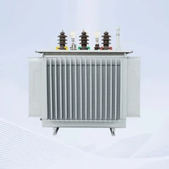




Winding Insulation Design & Temperature Rise Control of 1500kVA Oil Filled Transformer
When operating a high-capacity unit like the Winding Insulation Design & Temperature Rise Control of 1500kVA Oil Filled Transformer are the two pillars determining its lifespan and reliability.
As a leading ISO9001:2015 certified manufacturer with over 18 years of expertise and a 30,000㎡ smart factory, GNEE specializes in engineering power equipment that withstands extreme thermal and electrical stress. Poor insulation leads to short circuits; excessive temperature rise destroys windings.
In this technical deep-dive, we explain how GNEE optimizes both to deliver a 1500kVA Oil Filled Transformer that operates safely for 25+ years.


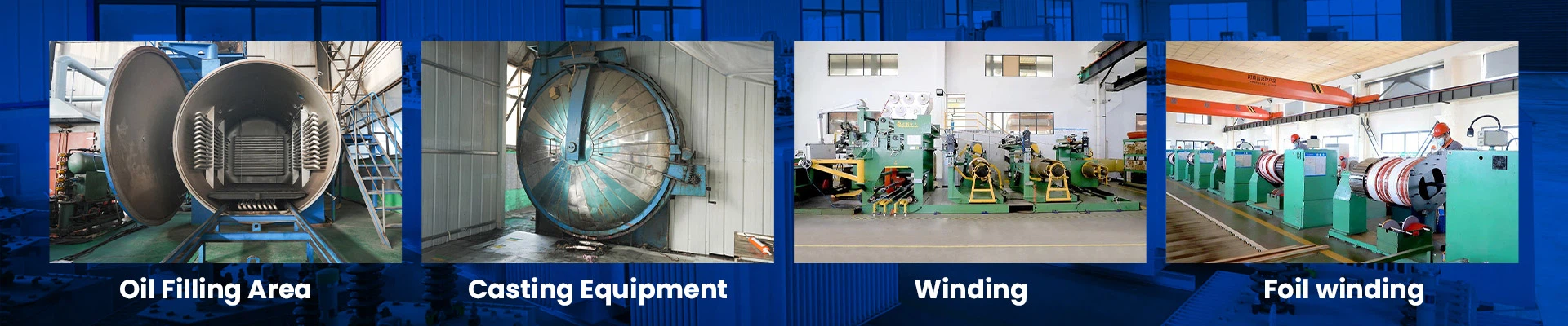
GNEE factory and warehouse for 1500kVA Oil Filled Transformer production
Who We Are: Your Trusted Transformer Engineering Partner
GNEE is not a generic reseller-we are a heavy-duty manufacturer with a 50,000-ton annual output. Our technical team comprises over 200 engineers who design and test every 1500kVA Oil Filled Transformer according to IEC 60076, ANSI C57.12, and GB 1094 standards.
From raw material inspection to final temperature rise testing, every process is controlled in-house. When you choose GNEE, you gain direct access to factory pricing, rigorous quality control, and customized insulation solutions tailored to your local grid conditions.
Understanding Winding Insulation Design in a 1500kVA Oil Filled Transformer
The Winding Insulation Design of a 1500kVA Oil Filled Transformer determines how well the unit resists electrical breakdown. Insulation must separate the high-voltage (HV) winding from the low-voltage (LV) winding, and both from the core and tank. Without proper insulation, partial discharge (PD) will erode the dielectric strength over time, leading to catastrophic failure.
Main Insulation vs. Turn-to-Turn Insulation
In a 1500kVA Oil Filled Transformer, insulation is classified into two categories:
Main Insulation: The barriers between HV and LV windings, and between windings and ground (core/tank). This is typically achieved with high-density pressboard barriers and transformer oil.
Turn-to-Turn Insulation: The enamel coating or paper wrapping on the copper or aluminum conductor itself. This prevents short circuits between adjacent turns.
Material Selection for High Reliability
GNEE exclusively uses Class A or Class B insulation systems (105°C to 130°C rating) for oil-immersed units. Our materials include:
- High-grade kraft paper wrapped around conductors for turn insulation.
- Pressboard cylinders for main insulation barriers.
- Mineral oil (or natural ester oil) serving as both coolant and dielectric fluid.
These materials are dried under vacuum to remove moisture, which drastically improves dielectric strength and reduces the risk of internal arcing.

Winding insulation design process for 1500kVA Oil Filled Transformer
Temperature Rise Control of 1500kVA Oil Filled Transformer – A Thermal Perspective
Temperature rise is the single biggest enemy of transformer longevity. The Temperature Rise Control of a 1500kVA Oil Filled Transformer refers to the difference between the winding/hot-spot temperature and the ambient cooling air temperature. For example, if ambient is 40°C and the average winding temperature is 105°C, the temperature rise is 65K (Kelvin).
Why Temperature Rise Matters
Every 8°C to 10°C increase above the rated insulation class cuts the transformer's life in half. High temperature accelerates:
- Oxidation of paper insulation (making it brittle).
- Sludge formation in the oil (reducing cooling efficiency).
- Expansion and contraction (leading to loose connections).
For a 1500kVA Oil Filled Transformer, standards limit the average winding temperature rise to 65K (for Class A insulation) and the hot-spot rise to 78K.
Calculating Losses That Generate Heat
Temperature rise is a direct result of internal losses:
- Load Losses (Copper Losses): Heat generated by I²R in the windings.
- No-Load Losses (Core Losses): Heat from hysteresis and eddy currents in the core.
GNEE uses advanced thermal simulation software to predict hotspots before building a single prototype. This allows us to optimize the design for uniform heat dissipation.
How GNEE Engineers Superior Winding Insulation Design for 1500kVA Oil Filled Transformers
Our engineering team follows a multi-step process to ensure the Winding Insulation Design of your 1500kVA Oil Filled Transformer exceeds IEC requirements.
Layer Winding vs. Disc Winding Selection
- LV Windings (Low Voltage): Typically layer wound with large cross-section copper foil or strip. This minimizes eddy losses and provides a smooth surface for insulation.
- HV Windings (High Voltage): Disc winding or interleaved disc winding to control voltage distribution and reduce impulse stress. Each disc is separated by pressboard spacers that create axial oil ducts for cooling.
Vacuum Pressure Impregnation (VPI) Process
Unlike cheap alternatives that skip this step, GNEE subjects all windings to a vacuum drying and oil impregnation cycle. Moisture is the enemy of insulation-a wet transformer can have 100x higher partial discharge than a dry one. Our VPI process ensures:
- Complete removal of air and moisture.
- Full penetration of oil into every microscopic void.
- Dielectric strength exceeding 40 kV/mm.
Insulation Coordination for Lightning Impulse
A 1500kVA Oil Filled Transformer connected to overhead lines must survive lightning strikes (1.2/50 µs impulse). GNEE designs insulation margins with:
- Electrostatic shields between HV and LV.
- Angle rings and grading rings to distribute electric field uniformly.
- Increased creepage distances on bushing turrets.

Temperature rise testing of 1500kVA Oil Filled Transformer
Active Temperature Rise Control Methods for 1500kVA Oil Filled Transformer
Controlling temperature rise is not passive-it requires intentional hydraulic and thermal design. GNEE implements three proven strategies to keep your 1500kVA Oil Filled Transformer cool.
Optimized Oil Duct Design
We calculate the exact size and placement of radial and axial cooling ducts within the winding stack. Wider ducts increase oil flow but reduce packing density. GNEE uses computational fluid dynamics (CFD) to find the sweet spot where oil velocity is high enough to carry heat away without causing turbulent hotspots.
Radiator Sizing and Oil Circulation
A standard 1500kVA unit may have 6 to 8 radiator panels. For high-ambient environments (deserts, tropical zones), GNEE offers:
- Larger radiators with increased fin surface area.
- Forced oil circulation (OF) with a pump to accelerate heat exchange.
- Forced air (AF) cooling fans that mount under radiators.
Fiber Optic Hot-Spot Monitoring (Optional)
For critical installations, GNEE can embed fiber optic probes directly into the HV and LV windings during manufacture. This provides real-time hot-spot temperature data, allowing predictive maintenance before the insulation degrades.
Technical Specifications Table – Winding Insulation & Temperature Rise
Below are the standard design parameters for a GNEE 1500kVA Oil Filled Transformer (11kV/0.4kV, Dyn11, 50Hz). These values ensure safe operation under continuous full load.
| Parameter | Specification | Notes |
|---|---|---|
| Rated Power | 1500 kVA | Continuous MVA rating |
| HV/LV Voltage | 11 kV / 0.4 kV | Custom voltages available |
| Insulation Class | Class A (105°C) | Or Class B (130°C) on request |
| Average Winding Temp Rise | ≤ 65 K | Measured by resistance method |
| Top Oil Temperature Rise | ≤ 60 K | Measured by thermometer |
| Hot-Spot Temperature Rise | ≤ 78 K | Calculated per IEC 60076-7 |
| Insulation Material | High-density pressboard + Kraft paper | Vacuum dried |
| Dielectric Strength (Oil) | ≥ 40 kV / 2.5 mm | Before and after thermal aging |
| Cooling Type | ONAN (Oil Natural Air Natural) | ONAN, ONAF, or OFAF options |
| Partial Discharge Level | ≤ 50 pC at 1.5 x voltage | Guaranteed for 1 minute |
| Reference Standard | IEC 60076, IEEE C57.12 | Full compliance certificate |
Conclusion: Secure Your Investment with GNEE's Expert Winding Insulation Design & Temperature Rise Control
The Winding Insulation Design & Temperature Rise Control of your 1500kVA Oil Filled Transformer directly determines its safety, efficiency, and lifespan. High-quality insulation prevents electrical breakdown, while precise thermal management avoids premature aging.
At GNEE, we combine advanced materials, vacuum processing, CFD simulation, and rigorous testing to deliver transformers that run cool and last decades.
Are you planning to procure a 1500kVA Oil Filled Transformer?
Don't leave reliability to chance. Contact GNEE today for a detailed technical proposal, insulation design drawing, and temperature rise guarantee. Ask us about our third-party test reports and live factory tour options. Let us engineer the reliability your project demands.
Can I upgrade the insulation class of my 1500kVA Oil Filled Transformer?
Yes. GNEE can design with Class B (130°C) or Class F (155°C) insulation using thermally upgraded paper and high-temperature oil (natural ester).
What happens if the temperature rise exceeds limits?
The transformer will suffer accelerated aging. Built-in winding temperature indicators (WTI) and oil temperature indicators (OTI) with alarm and trip contacts are standard to prevent this.
How does humidity affect winding insulation design?
Moisture drastically reduces dielectric strength. GNEE's factory maintains low humidity during assembly, and every transformer undergoes vacuum drying before oil filling.
What testing is required for a 1500kVA oil filled transformer?
1500kVA oil filled transformer testing includes routine tests such as winding resistance, turns ratio, impedance voltage, and insulation resistance, as well as type tests like temperature rise and short-circuit withstand tests.
How is a 1500kVA oil immersed transformer transported?
A 1500kVA oil immersed transformer is securely packed and transported on steel frames; depending on distance and regulations, it may be shipped with oil or in dry condition with oil filled on-site.
What precautions should be taken during transportation?
During transport, the 1500kVA oil filled transformer must be kept upright, protected from vibration, and sealed to prevent moisture ingress or contamination.
What are the installation requirements for a 1500kVA oil filled distribution transformer?
Installation requires a concrete foundation, proper grounding, oil containment measures, safe electrical clearance, and adequate ventilation or cooling space.
Can a 1500kVA oil filled transformer be installed indoors?
Yes, but indoor installation requires fire safety measures such as oil containment systems, fire barriers, and ventilation systems to ensure safe operation.
Send Inquiry