







Can A 2000 KVA Transformer And A 1600 KVA Transformer Operate In Parallel?
Jul 24, 2026
Leave a message
A 1600 kVA transformer and a 2000 kVA transformer can operate in parallel for short durations, provided that all four mandatory technical conditions for parallel operation are fully met. However, from the perspectives of engineering safety and full equipment service life, long-term full-load parallel operation is not recommended.
With a 20% capacity difference between the two units, the core bottleneck of parallel operation lies not in the feasibility of breaker closing, but in the high risk of load sharing deviation. The smaller-capacity transformer is highly prone to overload first, making the total power supply capacity fail to reach the theoretical combined value of 3600 kVA. The following sections provide a complete analysis covering prerequisites for parallel operation, capacity ratio calculation, core risks, and on-site operation recommendations.


I. Four Mandatory Prerequisites for Transformer Parallel Operation
Regardless of capacity consistency, all of the following conditions must be fully satisfied before any two transformers are connected in parallel. None can be omitted.
1. Identical Rated Voltage and Voltage Ratio
The rated voltages of both the high-voltage and low-voltage sides must be consistent, e.g. both 10 kV/0.4 kV.
The allowable deviation of the voltage ratio shall not exceed ±0.5%. Exceeding this range will generate no-load circulating current between windings.
The larger the voltage ratio difference, the greater the circulating current. In severe cases, it will directly burn out low-voltage windings, which is a Class I safety risk.
2. Identical Vector Group
The vector group designations of the two transformers must be exactly the same; Dyn11 is the most common configuration.
Parallel operation of one Dyn11 and one Yyn0 unit is strictly prohibited. A 30° phase difference will generate a massive short-circuit circulating current, which can cause equipment damage the instant the breaker closes.
Pay special attention to regional standard differences in overseas projects. Dyn11 is widely adopted in Europe, while some legacy projects use Yyn0. Always verify the nameplate before closing.
3. Closely Matched Short-Circuit Impedance (Uk%)
General industry standard: the difference in short-circuit impedance between the two transformers shall be less than ±10% to be qualified.
Example: if one unit has Uk = 6%, the impedance of the other shall fall within 5.4% to 6.6%.
Load sharing is inversely proportional to short-circuit impedance. The greater the impedance difference, the more severe the load deviation.
4. Consistent Phase Sequence
The A/B/C three-phase sequences on both the high-voltage and low-voltage sides must be connected correspondingly.
On-site phase verification must be performed with a phase tester before closing to confirm zero phase difference.
Incorrect phase sequence will cause a phase-to-phase short circuit in the low-voltage system, which is a serious operational accident.
II. Capacity Ratio Analysis for 2000 kVA and 1600 kVA Parallel Operation
When the Uk% values of the two transformers are exactly equal, the theoretical load sharing is linearly distributed by capacity ratio:
- Load share of the 2000 kVA transformer: 2000 ÷ (2000 + 1600) ≈ 55.6%
- Load share of the 1600 kVA transformer: 1600 ÷ (2000 + 1600) ≈ 44.4%
- Total theoretical capacity: 3600 kVA
However, this is a calculation result under ideal conditions. In practical engineering, the short-circuit impedances of two transformers with different capacities are almost never fully consistent:
- Typically, a 2000 kVA dry-type transformer has Uk ≈ 6%, while a 1600 kVA dry-type transformer has Uk ≈ 4% to 6%, varying by manufacturer and product series.
With only a 10% impedance deviation, the 1600 kVA smaller unit will reach full load first, while the 2000 kVA transformer still has substantial remaining capacity, resulting in underutilization of total capacity.
In extreme cases, the 1600 kVA transformer may already be overloaded when the total load reaches only 3000 kVA.
III. Three Core Risks of Parallel Operation with Different Capacities
1. Imbalanced Load Sharing and Overload of the Smaller Unit
This is the most prominent issue for parallel operation with a 20% capacity difference. Due to minor deviations in short-circuit impedance, load will shift to the side with lower impedance. Usually, the smaller-capacity transformer has relatively lower impedance and will bear a load exceeding its capacity proportion. Long-term overload accelerates insulation aging, shortens service life, and in severe cases triggers high-temperature tripping or even burnout.
2. Increased No-Load Circulating Current and Higher Additional Losses
The larger the capacity difference, the more obvious the no-load circulating current during parallel operation. This causes extra core and winding losses, leading to increased heat generation and reduced efficiency. For oil-immersed transformers, it also accelerates oil degradation; for dry-type transformers, it raises winding temperature rise and reduces insulation margin.
3. High Impact Risk During De-Paralleling and Fault Switching
At the moment the low-voltage bus tie breaker opens for de-paralleling, the entire load will transfer to a single transformer, which can easily cause overload tripping. If one unit trips out due to a fault, the other must withstand full load impact, which imposes higher requirements on protection setting calibration. Improper configuration may cause cascading tripping and expand the power outage scope.
IV. Special Notes on Dry-Type and Oil-Immersed Transformer Parallel Operation
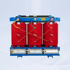
Dry-Type Transformers (SCB14/SCB18 Series)
Dry-type transformers have relatively poorer heat dissipation and are more sensitive to load deviation, so it is recommended to keep the total load factor at a lower level after parallel connection.
They can withstand higher loads for short periods under forced air cooling (AF) conditions, but for long-term parallel operation, the load should still be kept within 80% of rated capacity.

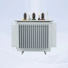
Oil-Immersed Transformers (S11/S13 Series)
Oil-immersed transformers have stronger heat dissipation and slightly higher overload tolerance than dry-type units, but oil degradation caused by circulating current cannot be ignored.
When transformers with different cooling methods (ONAN/ONAF) operate in parallel, the load shall be limited based on the unit with lower cooling capacity.

Note: Parallel operation of one dry-type and one oil-immersed transformer is not recommended. The two have significant differences in impedance characteristics and temperature rise curves, leading to high complexity in load sharing calculation and significantly elevated operation risks.
V. On-Site Operation Recommendations
If the project does require parallel operation of 2000 kVA and 1600 kVA transformers, follow these principles:
Only for emergency and peak-load temporary use: Treat parallel operation as a backup or peak-load supplement, not a normal long-term power supply mode. Prioritize single-unit operation daily, and use short-term parallel operation only during peak load periods.
Strictly control total operating load: Keep the total load within 2800–3000 kVA to ensure the load factor of the 1600 kVA transformer does not exceed 85%, with a safety margin reserved.
Install real-time current monitoring: Fit ammeters and load monitoring devices on each low-voltage incoming side to track load sharing of the two transformers in real time, and adjust promptly if deviation occurs.
Strictly enforce phase verification procedures: Before the first closing, perform dual phase verification on both high-voltage and low-voltage sides with a professional phase tester to confirm correct phase sequence and phase alignment.
Optimize protection settings: Adjust overcurrent protection and high-temperature alarm settings to ensure priority alarm when the smaller-capacity transformer is overloaded, avoiding direct tripping.
VI. Absolute Red Lines for Prohibited Parallel Operation
Parallel closing is strictly prohibited under any of the following circumstances:
- Voltage ratio deviation exceeds ±0.5%
- Mismatched vector group designations
- Short-circuit impedance difference exceeds ±10%
- Inconsistent phase sequence or phase deviation
- Insulation defect or hidden fault in either transformer
Conclusion
Parallel operation of 2000 kVA and 1600 kVA transformers is technically feasible, provided that the four parallel operation conditions are strictly met and the load level is controlled. Long-term full-load operation is not recommended. For long-term stable power supply demand, a better solution is to select two transformers of the same capacity for parallel operation, or configure a more reasonable capacity combination after load recalculation.
If you are planning a distribution capacity expansion project, unsure whether your existing transformers can operate in parallel, or need a customized technical solution for parallel operation, contact our technical team for a free transformer parallel operation feasibility assessment report and capacity ratio optimization proposal. We can deliver professional operation schemes and protection configuration recommendations based on your on-site conditions, load characteristics and equipment parameters, and also supply a full range of dry-type and oil-immersed transformers with technical support.
Send Inquiry