







2000 kVA Transformer Current Capacity and Voltage Conversion: A Complete Technical Guide
What Is a 2000 kVA Transformer?
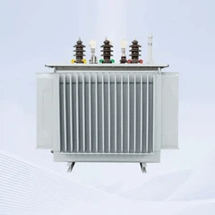
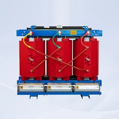
A 2000 kVA transformer is a three-phase power transformer with a rated apparent power of 2000 kilovolt-amperes, which equals 2 MVA. It is most commonly applied to step down medium voltage, such as 11 kV or 33 kV, to low voltage, such as 400 V or 690 V, for industrial and commercial end users. The same machine can also step up generator voltage for grid export in renewable energy plants. Its design follows the rating, temperature and cooling requirements defined in IEC 60076-1 and IEC 60076-2, and it is intended for continuous operation at rated load within the specified temperature rise limits.
How to Calculate the Current Carrying Capacity
The current carrying capacity of a 2000 kVA transformer defines the maximum continuous load current on each winding without exceeding the thermal limits. Because it is not a single fixed value, it must be calculated for the actual operating voltage of each side. For a three-phase transformer, the line current is given by the fundamental formula:
I (A) = S (kVA) × 1000 / (√3 × V (V))
The table below applies this formula to the voltage configurations most frequently specified for a 2000 kVA transformer.
| Voltage Level | Full Load Line Current | Typical Side |
|---|---|---|
| 33 kV | 35 A | Primary high voltage |
| 11 kV | 105 A | Primary high voltage |
| 0.69 kV | 1673 A | Secondary low voltage |
| 0.4 kV | 2887 A | Secondary low voltage |
The low-voltage side at 400 V demands busbars, links and connections rated well above 3000 A, and the winding conductor cross-sections are selected with a current density that prevents local hot spots, typically 2 to 3 A per square millimetre for copper.
Thermal Limits and Overload Performance
The practical current carrying capacity is governed by the insulation class and the cooling method. For an oil-immersed unit with ONAN cooling, the average winding temperature rise is limited to 65 K and the hot-spot temperature rise to 78 K, in line with IEC 60076-2 and the loading guide IEC 60076-7. Short-time overloads of about 10 to 20 percent above rated current can be tolerated for limited periods without significant loss of insulation life, provided the oil and winding temperatures are monitored. Units with forced cooling, such as ONAF, support higher short-term peaks, which makes them suitable for fluctuating load profiles in commercial buildings and data centres.
Voltage Conversion Principles
Voltage conversion in a 2000 kVA transformer follows the turns ratio principle: the induced voltage in each winding is proportional to the number of turns, while the transferred power remains nearly constant apart from losses. The impedance voltage, typically in the range of 4.5 to 7 percent for this rating, determines the voltage drop under load and limits the short-circuit current. To keep the output voltage stable when the primary voltage fluctuates, tap changers are fitted on the high-voltage winding, commonly with a range of ±2×2.5 percent or ±5 percent; off-circuit tap changers are adjusted with the unit de-energized, while on-load tap changers allow adjustment without interrupting the supply.
Technical Parameters of a Typical 2000 kVA Transformer
| Parameter | Specification |
|---|---|
| Rated capacity | 2000 kVA |
| Primary voltage | 11 kV or 33 kV, customizable |
| Secondary voltage | 0.4 kV or 0.69 kV, customizable |
| Frequency | 50 Hz or 60 Hz |
| Phases | Three-phase |
| Cooling method | ONAN, ONAF or OFAF |
| Winding material | Copper or aluminium |
| Insulation class | Class A for oil-immersed units |
| Impedance voltage | 4.5 to 7 percent |
| Temperature rise | 65 K average winding, 78 K hot spot |
| Tapping range | ±2×2.5 percent off-circuit or on-load |
| Vector group | Dyn11, Yyn0 or as required |
| Standards | IEC 60076, IEEE C57.12.00 |
Applications and Load Considerations
A 2000 kVA transformer suits medium-scale industrial plants, commercial complexes, hospital and campus networks, mining operations and renewable energy collector substations. When specifying the unit, evaluate the total connected load in kW, the power factor, the diversity factor and the expected load growth over five to ten years, and reserve a capacity margin of 10 to 20 percent. Protection should include overcurrent and earth fault relays, an oil temperature indicator with alarm and trip contacts, and a Buchholz relay for sudden pressure and gas accumulation in liquid-filled units. Routine testing before commissioning includes turns ratio, winding resistance, insulation resistance and impedance voltage measurement in accordance with IEC 60076-1.
FAQ
Q: What is the full load current of a 2000 kVA transformer at 11 kV?
A: Approximately 105 A, calculated as 2000 × 1000 divided by the product of √3 and 11000 V.
Q: What is the full load current on the 400 V side?
A: Approximately 2887 A, which is why the low-voltage connections, busbars and protection devices must be rated well above 3000 A.
Q: What does ONAN cooling mean?
A: It means oil natural air natural: the oil circulates by natural convection and dissipates heat through the tank and radiators without pumps or fans, as defined in IEC 60076-2.
Q: Why is the impedance voltage important?
A: The impedance voltage, typically 4.5 to 7 percent, limits the short-circuit current and determines the voltage drop under load; lower impedance gives better voltage regulation but increases mechanical stress during faults.
Q: Can a 2000 kVA transformer be overloaded?
A: Short-time overloads of 10 to 20 percent are possible without serious loss of insulation life, but the oil and winding temperatures must be monitored; sustained overload reduces insulation life exponentially according to the loading guide IEC 60076-7.
Q: What information should be provided when specifying a 2000 kVA transformer?
A: Capacity, primary and secondary voltages, frequency, cooling method, vector group, impedance, winding material, tapping range, installation location and the applicable standards of the destination country.
Send Inquiry