









20 kV Fully Sealed Three-Phase Low-Loss Distribution Transformer: Data and Design
Nov 11, 2025
Leave a message
Why 20 kV Distribution Is Specified
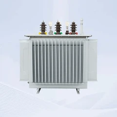
A 20 kV medium-voltage network carries roughly twice the power of a 10 kV feeder over the same conductor cross-section, which reduces line losses and the number of substations needed to serve a given load area. It is applied in dense urban distribution, industrial parks, mining sites and the collector circuits of wind and solar plants. The fully sealed three-phase oil-immersed transformer at the interface steps 20 kV down to 0.4 kV or 0.415 kV, and many designs accept a 20 kV or 10 kV primary so that one unit can serve either network voltage.
Standard capacity coverage runs from 50 kVA to 5000 kVA, at 50 Hz or 60 Hz, with ONAN cooling and a copper winding.
20 kV Series Specification
| Capacity (kVA) | No-load loss (kW) | Load loss (kW) | No-load current (%) | Impedance (%) |
|---|---|---|---|---|
| 50 | 0.13 | 0.96 | 2.0 | 5.5 |
| 100 | 0.20 | 1.65 | 1.6 | 5.5 |
| 200 | 0.33 | 2.86 | 1.3 | 5.5 |
| 400 | 0.57 | 4.73 | 1.0 | 6.0 |
| 630 | 0.81 | 6.82 | 0.9 | 6.0 |
| 1000 | 1.15 | 11.33 | 0.7 | 6.0 |
| 1600 | 1.63 | 15.95 | 0.6 | 6.0 |
| 2500 | 2.34 | 22.22 | 0.5 | 6.0 |
Primary tapping is plus/minus 5 % or plus/minus 2 x 2.5 %, off-circuit, with a voltage combination such as 20 kV / 10 kV on the high-voltage side. Short-circuit impedance for the 20 kV class is higher than for a 10 kV unit of the same rating, typically 5.5 % up to 315 kVA and 6 % above, because the higher system voltage requires a stiffer winding geometry to control short-circuit forces.
Low-Loss Core Design
| Model | Capacity (kVA) | No-load loss (W) | Load loss (W) | No-load current (%) |
|---|---|---|---|---|
| S13-M-100 | 100 | 150 | 1580 | 1.8 |
| S13-M-250 | 250 | 290 | 3200 | 1.4 |
| S13-M-630 | 630 | 570 | 6200 | 1.1 |
| S13-M-1000 | 1000 | 830 | 10300 | 1.0 |
| S13-M-1600 | 1600 | 1170 | 14500 | 0.8 |
| S13-M-2000 | 2000 | 1510 | 17800 | 0.8 |
| S13-M-2500 | 2500 | 1780 | 20700 | 0.7 |
The stepped-lap core is built from thin, surface-insulated grain-oriented silicon steel laminations of the class specified in standards such as ASTM A876. Step-lap joints reduce the air-gap reluctance at the corners, which is where a significant share of no-load loss is generated, and vacuum drying of the assembled core and coils removes moisture from the paper insulation before oil filling.
Enclosure, Protection and Sealed Tank
The corrugated tank withstands the internal pressure generated by an arcing fault, dissipates heat through its wall area and absorbs oil expansion in place of a conservator, so the oil never contacts air. Where the site protection scheme requires it, a Buchholz relay (gas relay) is mounted in the pipe between the tank and any oil storage vessel: decomposition gas or an oil surge produced by an internal fault operates the contacts, which trip the transformer or raise an alarm before the fault develops further. A pressure relief device, oil-level indication and a clearly marked earthing terminal are standard. Terminal arrangements carry wiring identification to simplify commissioning.
Losses, Insulation and Temperature Limits
Design and testing follow IEC 60076-1 for general requirements and loss and impedance measurement, IEC 60076-2 for temperature rise, and IEC 60076-3 for insulation levels. For the 24 kV equipment class applicable to a 20 kV winding, IEC 60076-3 sets a lightning impulse withstand of 125 kV peak and a power-frequency withstand of 50 kV rms. Temperature rise is limited to a 60 K top-oil rise and a 65 K average winding rise for ONAN cooling with mineral oil, so the corrugated wall and the oil volume are sized to the actual load profile rather than to the nameplate rating alone.
Frequently Asked Questions
Q: Can one transformer accept either 20 kV or 10 kV on the primary?
A: Yes. Dual-ratio designs are built with a primary rated for the 20 kV class and tapping or winding arrangements that allow operation at 10 kV, which simplifies spares holding where both network voltages exist.
Q: What is the rated capacity range?
A: The sealed three-phase series covers 50 kVA to 5000 kVA. The most frequently ordered ratings for a 20 kV / 0.4 kV interface are between 100 kVA and 2000 kVA.
Q: Why is the impedance of a 20 kV transformer higher than a 10 kV unit?
A: The higher system voltage produces larger short-circuit forces for the same kVA, and a higher impedance voltage reduces prospective fault current and the mechanical stress on the windings. The standard series uses 5.5 % to 6 %.
Q: What does the Buchholz relay protect against?
A: Slow-developing internal faults. Gas produced by oil decomposition or an oil surge operates the relay contacts, which can alarm or trip the unit depending on the protection setting.
Q: How often is oil maintenance required on a sealed 20 kV unit?
A: No oil change is required in normal service because the tank is sealed. Annual inspection covers bushings, tank joints and cleanliness, while oil sampling for moisture, acidity and dielectric strength is placed on a multi-year cycle.
Send Inquiry