


What Is The Purpose Of An Oil Transformer?
Nov 12, 2025
Leave a message
What Is an Oil-Immersed Transformer?
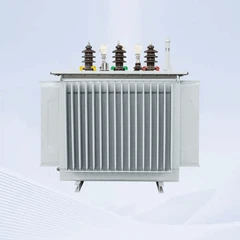
An oil-immersed transformer is a type of power transformer in which the magnetic core and windings are fully submerged in insulating oil. This oil serves dual functions: it electrically insulates the energized components and dissipates heat generated during operation by circulating through radiators. These transformers are widely used in high-voltage transmission networks, substations, industrial facilities, and renewable energy projects due to their reliability and thermal efficiency.
Oil-immersed transformers are engineered to handle voltages from 6.6 kV to 765 kV and capacities from 50 kVA to 1000+ MVA, making them ideal for grid-level applications.
In modern electrical power systems, voltage must be transformed efficiently and safely across various stages-from generation to consumption. For medium to ultra-high voltage applications, oil-immersed transformers are the industry standard because they offer reliable insulation, superior cooling, and proven long-term durability. The defining feature of these transformers is their use of insulating oil, which submerges the internal components and acts as both a dielectric insulator and heat transfer medium.
What Is The Purpose Of An Oil Transformer?
An oil-filled transformer is a voltage transformer that cools the oil inside to lower the temperature. Its body is typically mounted on a large welded steel tank filled with insulation oil.
The oil-based transformer uses insulators for high-voltage electrical parts like switches, condensers, converters, and circuit breakers. Once the device is switched on, the coil and iron core heat is converted into insulation oil, transforming it into a cooling agent.
Transmission lines and electrical substations frequently use transformers that operate on oil. Its core and coils are cooled and insulated by submerging them in oil. In a convection-driven system, oil circulates via ducts in the coil and then wraps around the core.
What's Inside An Oil Transformer?
When the capacity of the tank is low, air flow from outside the container cools the oil.
In greater ratings, an air-cooled radiator serves as the oil's cooling source.
Generally, transformer oils are made to function well at extremely high temperatures, insulating, cooling, and preventing corona discharges and overheating.
Key Components and Functions of an Oil-Immersed Transformer
| Component | Function |
|---|---|
| Magnetic Core | Directs magnetic flux to enable voltage transformation |
| Windings (HV/LV) | Carry electrical current; insulated and submerged in oil |
| Insulating Oil | Prevents electrical breakdown and removes heat |
| Main Tank | Holds the oil and active components in a sealed steel enclosure |
| Radiators / Coolers | Dissipate heat from the circulating oil to ambient air |
| Conservator Tank | Accommodates thermal oil expansion and contracts as temperatures change |
| Breather (Silica Gel) | Filters out moisture during air exchange in conservator system |
| Buchholz Relay | Detects internal faults by gas accumulation in the oil |
| Pressure Relief Valve | Releases internal overpressure in emergency conditions |
Main Types of Oil-Immersed Transformers
| Classification Criterion | Types |
|---|---|
| Cooling Method | ONAN, ONAF, OFAF, OFWF (Oil/Air/Natural/Forced combinations) |
| Oil Preservation | Conservator-type (with breather) vs Hermetically sealed (airtight) |
| Core Design | Core-type (standard) vs Shell-type (compact, high-strength) |
| Phase Configuration | Single-phase (modular) vs Three-phase (common in grid applications) |
Iron Center
The transformer's iron core is the principal magnetic link, and it is the component capable of magnetism conductance. It transforms the magnetic energy into electrical energy for the secondary circuit and the electric power of the main circuit into magnetic energy.
Typically, silicon steel sheets are arranged to form the iron core of a transformer, and they are isolated from one another. The silicon steel sheet mostly influences the transformer's no-load loss.
Transformer Loop
The primary winding and the secondary winding are two different windings that make up any type of transformer. The primary winding is connected to the power source, and the secondary winding is connected to the load.
Within the same iron core column, the first and second windings of every phase of a three-phase transformer are wrapped into cylindrical shapes. The low-voltage winding can easily isolate the core in this position.
A space is left between the high and low windings to serve as an oil route, which allows the transformer oil to circulate and help in thermal transfer.
Oil Conservator
The transformer oil conservator is also known as the oil pillow since it resembles a cylindrical pillow. It is mounted horizontally above the oil reservoir and is pumped into the transformer's oil tank.
Typically, the capacity of the oil conservator is 10% or less of the volume of the storage tanks.
Once the transformer oil is heated and expands, it moves from the oil tank into the oil conservator; the transformer oil contracts once it's cold and is refilled from the oil conservator to the oil reservoir.
Transformer Bushing
The guide rod serves as the connection between the transformer winding lead wire and the external circuit. The transformer bushing is an insulator between the guide rods and the box lid and keeps the guide rod in place.
Transformer Breather
Power transformer protection includes the use of pressure relief equipment. If an internal defect or short circuit arises in an oil-immersed transformer, arcing will immediately evaporate the oil, causing the temperature in the transformer tank to rise rapidly.
It is necessary to take precautionary measures because if the pressure is not released immediately, the oil tank can break, resulting in an explosion and fire.
Tap Changer
When utilized for the on-load voltage-controlling transformer, the oil conservator has a switch oil conservator placed at the bottom without capsules called the tap changer.
Oil Purifier
The oil purifier is an installation on the sidewall of the transformer or the lower portion of the strong oil cooler that contains an adsorbent: silica gel or activated alumina.
Key Advantages of Oil-Immersed Transformers
| Advantage | Explanation |
|---|---|
| High Voltage Capability | Handles up to 765 kV due to superior dielectric performance |
| Efficient Cooling | Oil convection supports long duty cycles and thermal balance |
| Long Service Life | Often exceeds 30–50 years with regular oil maintenance |
| Scalable Design | Supports custom power ratings and voltage classes |
| Monitoring Integration | Compatible with DGA, thermal, and moisture sensors |
Safety and Environmental Considerations
| Risk Factor | Control Measures |
|---|---|
| Fire Hazard (Mineral Oil) | Use fire barriers, mineral oil alternatives (ester), or detectors |
| Moisture Contamination | Maintain breather, seal integrity, periodic oil testing |
| Oil Leakage Risk | Use bund walls, leak alarms, maintenance inspection |
| Thermal Overload | Install RTDs, cooling fans, and overload relays |
Common Application Environments
| Sector | Typical Installations |
|---|---|
| Utilities | Transmission and distribution substations |
| Industrial Plants | Load centers, process control, motor drives |
| Renewables | Solar PV substations, wind turbine collection points |
| Transport | Railway traction substations, metro power feeds |
| Infrastructure | Airports, data centers, and critical facilities |
Cooling Code Format Explained
Each transformer cooling code consists of four letters, divided into two pairs:
| Code Segment | Meaning |
|---|---|
| 1st & 2nd | Internal fluid type and movement (O = oil; N = natural, F = forced) |
| 3rd & 4th | External medium and movement (A = air; W = water; N = natural, F = forced) |
For example:
ONAN = Oil Natural Air Natural
ONAF = Oil Natural Air Forced
OFAF = Oil Forced Air Forced
OFWF = Oil Forced Water Forced
Cooling Method Comparison Table
| Cooling Method | Internal Oil Flow | External Cooling Medium | Cooling Devices | Power Range | Application Scope |
|---|---|---|---|---|---|
| ONAN | Natural convection | Natural air | Radiators only | Up to 10–25 MVA | Distribution transformers, small substations |
| ONAF | Natural | Forced air (fans) | Radiators + fans | 25–60 MVA | Industrial, urban substations |
| OFAF | Forced oil (pumps) | Forced air (fans) | Pumps + fans | 60–200+ MVA | Large grid transformers, heavy load |
| OFWF | Forced oil | Forced water | Pumps + water coolers | 200–1000+ MVA | Power plants, offshore, nuclear, or confined environments |
Typical Performance Impact
| Cooling Method | Max Temperature Rise (°C) | Relative Cooling Efficiency | Load Rating Boost |
|---|---|---|---|
| ONAN | 55–65 | Baseline | 1× |
| ONAF | 45–55 | +30–40% | 1.4× |
| OFAF | 35–45 | +50–60% | 1.6–1.8× |
| OFWF | 30–40 | +70–90% | 2.0× or more |
Use Case Matching Guide
| Scenario | Best Cooling Method | Reason |
|---|---|---|
| Rural or standard utility use | ONAN | Low load, low noise, low complexity |
| Medium-load industrial use | ONAF | Occasional boost cooling during peak demand |
| Grid transformer with constant heavy load | OFAF | High power transfer, continuous cooling needed |
| Indoor or closed-loop cooling | OFWF | No air ventilation allowed; heat must go to water |
ONAN/ONAF dual-rated designs are common to increase rating flexibility.
Equipment and Components by Method
| Method | Cooling Equipment Used |
|---|---|
| ONAN | Radiators, expansion tank (passive airflow) |
| ONAF | Radiators, thermostatically controlled axial fans |
| OFAF | Oil pumps, fans, radiator banks, directional valves |
| OFWF | Oil pumps, water-to-oil heat exchangers, filtration units |
Send Inquiry