










How to Choose a DC EV Charger for Different Charging Applications?
Oct 28, 2026
Leave a message
What Is a DC EV Charger and How Does DC Fast Charging Work?

A DC EV charger (also called a DC fast charger or rapid charger) performs the AC-to-DC conversion outside the vehicle and feeds direct current straight into the battery pack. An AC wallbox, by contrast, hands over alternating current and lets the car's small onboard charger do the conversion - which is why AC charging is typically capped at 7–22 kW while DC charging starts around 20 kW and runs past 350 kW.
The conversion chain is simple to describe and important to specify correctly:
- Grid intake - three-phase AC (400 V in the EU, 480 V in North America, 11–33 kV where a dedicated transformer is installed).
- Rectification - an active front-end rectifier with power-factor correction converts AC to DC. Modern units keep input power factor above 0.99 and current THD below 5%, which matters if your utility imposes IEEE 519 or EN 61000 harmonic limits.
- DC delivery - the charger negotiates voltage and current with the vehicle over the control pilot (IEC 61851-23 for DC, IEC 61851-24 for digital communication).
- Battery management control - the vehicle's BMS, not the charger, decides the actual charge curve. This is the single most overlooked fact in procurement.
Small Tip - design logic: Start every specification from a stopwatch, not a catalogue. Time the vehicle's actual dwell time, then work backwards to power. Specifying maximum kW for a site where cars park for six hours buys capacity you will never convert into revenue.
Because the BMS governs the curve, a charger's rated output is an upper envelope, not a guarantee. Between roughly 10% and 80% state of charge, most modern packs accept their peak rate; above 80%, current tapers sharply. That is why the industry publishes "10–80%" times and why the honest comparison metric is kWh delivered per hour of bay occupancy, not peak kW.

How Do You Size DC Charger Power for Public, Fleet, and Highway Sites?
The right power class follows the application. The table below consolidates the mainstream bands used by public operators, fleet depots, and highway concessionaires in 2026.
|
Charging application |
Recommended DC charger power |
Typical connector set |
Main design driver |
|
Urban public charging hub |
60–150 kW |
CCS2 + CHAdeMO or CCS1 + NACS |
Vehicle turnover and bay utilisation |
|
Highway service area / rest stop |
150–350 kW |
CCS2 (liquid-cooled above 200 A) |
Minimum dwell time, queue length |
|
Commercial fleet depot |
60–150 kW per bay |
CCS2 or CCS1, dual-gun preferred |
Overnight window and schedule certainty |
|
Logistics and last-mile delivery |
20–60 kW |
CCS2/CCS1, GB/T in China |
Number of bays vs. available capacity |
|
Shopping mall, hotel, workplace |
30–60 kW |
CCS2 + Type 2 AC fallback |
1–2 hour dwell, revenue per visit |
|
Space-constrained urban site |
20–40 kW wall-mounted |
CCS2 or CCS1 |
Floor area and cable routing |
|
Roadside assistance, temporary sites |
30–40 kW portable |
CCS1/CCS2/GB/T/CHAdeMO/NACS |
Mobility and plug-and-play setup |
|
Remote or off-grid location |
40–80 kW battery-integrated |
CCS2 or CCS1 |
Energy storage and solar integration |
Fleet sizing, worked end to end. Twenty electric delivery vans, each returning with roughly 40 kWh of daily energy demand, require 800 kWh per night. With an eight-hour charging window, the theoretical average power is 800 ÷ 8 = 100 kW. Add conversion losses (typically 5–8% at this power level) and a margin for winter efficiency, and a 120–150 kW installation is the defensible answer - not a 300 kW unit, and not ten 20 kW boxes either.
Small Tip - cost-scope trap: Quotes are compared per kW of nameplate, but value is delivered per kWh. Ask every vendor for one number: guaranteed kWh delivered per bay per night at your ambient temperature. Two chargers with identical nameplates can differ by 15% on that figure because of derating behaviour.
Which Connector Standards and Communication Protocols Does Your DC Charger Need?

Connector choice is a geography problem disguised as an engineering problem. Get it wrong and the site is stranded.
|
Standard |
Primary markets |
Typical DC power |
2026 status |
|
CCS2 (Combo 2) |
EU, UK, most of Asia, Oceania |
up to 350 kW (liquid-cooled to 500 A) |
Default for new public infrastructure |
|
CCS1 (Combo 1) |
North America, Korea |
up to 350 kW |
Widely deployed; coexisting with NACS |
|
NACS |
North America (Tesla-origin) |
up to 250 kW+ on current versions |
Rapidly becoming mandatory on new NA models |
|
GB/T |
China |
up to 250 kW |
Mandatory for the domestic market |
|
CHAdeMO |
Japan, legacy fleets |
up to 100–200 kW (3.0/3.1) |
Legacy support only for most new builds |
Two specifications beyond the plug itself deserve explicit lines in your RFQ:
- Output voltage window. 800 V vehicle platforms are now mainstream. A charger limited to 500 V DC simply cannot serve them at full rate. Specify a 150–1000 V DC output range unless your fleet is entirely 400 V.
- Backend protocol. Insist on OCPP 1.6J as a floor and OCPP 2.0.1 if you plan smart charging, ISO 15118 Plug & Charge, or vehicle-to-grid pilots. Without OCPP you are locked to one software vendor for the life of the asset.
Small Tip - modelling error to avoid: Do not size the transformer from charger nameplate in kW. The grid sees kVA, and the gap is efficiency and power factor. A 120 kW charger running at 95% efficiency and 0.99 power factor draws about 126 kVA. Multiply the error across six bays and you have undersized a transformer by more than 150 kVA.
How Much Grid Capacity and Transformer Rating Does a DC Charging Site Require?
This is the section most charger buying guides skip, and it is where projects actually fail. A DC fast charging site is a power distribution project with a charger attached, and the transformer, switchgear, and distribution cabinet are usually 20–35% of total capex.
The sizing method, step by step:
Sum the rated AC input of all chargers: charger kW ÷ efficiency ÷ power factor.
Multiply by a diversity factor - 0.6–0.8 for depots with long, scheduled parking windows; 0.85–1.0 for highway sites where arrivals are random and peak stacking is real.
Add site loads: lighting, HVAC, payment kiosks, canopy, and any workshop equipment (typically 10–20 kVA).
Select the next standard rating above the result, then check voltage drop on the 400 V run and the prospective short-circuit current at the distribution board.
Worked example - fleet depot, six 120 kW dual-gun chargers:
- AC input per charger: 120 ÷ 0.95 ÷ 0.99 ≈ 126 kVA
- Gross simultaneous load: 6 × 126 = 758 kVA
- With 0.7 diversity (overnight window, dynamic load management active): 531 kVA
- Site auxiliary loads: +25 kVA → 556 kVA
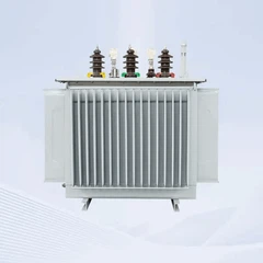
- Selected: 630 kVA dry-type transformer, 11 kV / 0.4 kV, Dyn11, IEC 60076
Worked example - highway hub, six 240 kW chargers:
- AC input per charger: 240 ÷ 0.95 ÷ 0.99 ≈ 252 kVA
- Gross simultaneous load: 1,512 kVA
- With 0.8 diversity: 1,210 kVA
- Site auxiliary loads: +40 kVA → 1,250 kVA
- Selected: 1,600 kVA cast-resin or oil-immersed transformer, with a 2,000 kVA unit if a second phase is planned
Still unsure which power band fits your site?
Send us three numbers - fleet size, average daily kWh per vehicle, and your available charging window - and we will tell you which power class you actually need, with the calculation shown.
Small Tip - comparison method that actually works: Compare bids on cost per delivered kWh over five years, not cost per kW. Include transformer losses (a 630 kVA unit idling costs real money every hour of every year), demand charges, maintenance, and expected uptime. A charger that is 12% cheaper but 3% less efficient loses on a 60-bay site.
Two further grid-side checks routinely get missed:
- Harmonics and flicker. Six-pulse rectifiers without active PFC can breach utility limits. Require measured THD data at partial load, not just at full load - partial load is where many units behave worst.
- Derating for site conditions. Above 1,000 m altitude or 40 °C ambient, both chargers and transformers derate. A site in a hot, high-altitude location can lose 10–15% of usable output, and that must be in the specification, not discovered at commissioning.
What Determines the Total Cost of Ownership of a DC Fast Charging Site?
Hardware is typically half the story. A realistic five-year model includes:
- Charger hardware - and the delta between air-cooled and liquid-cooled is significant.
- Grid-side equipment - transformer, MV/LV switchgear, distribution cabinet, cabling, earthing, civil works.
- Installation and commissioning - including any utility contribution.
- Software and connectivity - OCPP backend, payment terminal, SIM/data, PCI-DSS scope if you take card payments.
- Energy - import tariff, demand charges, and the value of load management in shaving peaks.
- Maintenance and uptime - a public site at 95% uptime versus 99% uptime is a material revenue difference when bay-hour is your product.
- Expansion - spare wayleaves, spare transformer capacity, and spare breaker positions are cheap at design stage and expensive later.
Plan expansion explicitly. Reserve 20–30% headroom in transformer capacity and ducting at the first phase. Confirm that the existing grid connection can carry a second phase, check that the charger supports dynamic power allocation so added units share a fixed envelope, and verify connector and protocol coverage against vehicles you expect to buy in three years - not the ones you own today.
One RFQ, one responsible party. Charger vendors and power-equipment vendors quoting separately is the most common source of mismatch on charging projects - the transformer arrives rated for the wrong diversity assumption, or the distribution cabinet lacks the breaker ways for phase two. Bundle the transformer, switchgear, and distribution cabinet into a single enquiry with your charger specification attached, and the interface risk disappears. Request a bundled quotation at https://www.gneeelectric.com/contact-us.


Get Your Charging Site Power Package
We supplies the power side of DC fast charging projects - 50 kVA to 2,500 kVA oil-immersed and dry-type transformers, prefabricated and containerised substations, MV/LV switchgear, and IP-rated distribution cabinets - engineered for EV charging stations, solar farms, and commercial power systems, with 18+ years of export experience into 150+ countries.
Send us four numbers and we will return a matched configuration:
- Number of charge points and rated power per point
- Available grid voltage and capacity (11 kV / 20 kV / 33 kV, kVA available)
- Daily charging window and expected kWh demand
- Target connector standards (CCS1 / CCS2 / NACS / GB/T / CHAdeMO)
What you get back within one business day: a transformer rating recommendation with diversity assumptions, a matched switchgear and distribution cabinet bill of materials, and a budgetary quotation - free of charge, no obligation.
Send Inquiry