







Power Transformers: Uses, Classification, and Model Interpretation
Apr 01, 2026
Leave a message
Power transformers are static electrical energy converters that transmit electrical energy without changing its frequency. As one of the most critical and widely used equipment in power systems, the total installed capacity of transformers is more than 9 times that of generators. They play an irreplaceable role in voltage conversion, power transmission, distribution, and end-user power supply, and are the core guarantee for the safe, stable, and efficient operation of the global power grid.
At GNEE ELECTRIC, we specialize in manufacturing high-performance power transformers tailored to diverse global power grid requirements, from large-scale power transmission projects to industrial and commercial distribution systems.
This guide will comprehensively explain the uses, classification, and model interpretation of power transformers, helping you select the most suitable transformer solutions for your projects.
Core Uses of Power Transformers
Voltage Conversion for Efficient Power Transmission
According to the power transmission formula P=UI, when transmitting the same power, the higher the voltage, the smaller the current. This principle directly reduces line power loss and allows for smaller conductor cross-sections, cutting metal material costs for transmission lines.
- Step-up transformers: Generators can only output low voltage (usually below 20kV) due to manufacturing limitations. Step-up transformers boost the voltage to ultra-high levels (35kV, 66kV, 110kV, 220kV, 330kV, 500kV, etc.) for long-distance power transmission to remote load centers.
- Step-down transformers: At the user end, step-down transformers reduce the high transmission voltage to safe, usable levels (e.g., 10kV, 0.4kV) for industrial, commercial, and residential electrical equipment. Terminal substation step-down transformers are also called distribution transformers.

High-Efficiency Energy Transmission
Power transformers have extremely high transmission efficiency:
- Small and medium-sized transformers: Efficiency ≥ 95%
- Large-scale power transformers: Efficiency up to 98% or higherWhile there is a small amount of active loss during operation, it is negligible compared to the huge energy savings brought by high-voltage transmission, making transformers the most cost-effective equipment in power systems.
Power System Voltage Regulation and Stability
- Transformers with on-load or no-load tap-changers can adjust the output voltage in real time, compensating for voltage fluctuations caused by load changes, ensuring stable power supply to end users, and maintaining the safe operation of the power grid.
Comprehensive Classification of Power Transformers
Power transformers can be classified by multiple dimensions to meet different application scenarios. Below is the standard classification system widely adopted in the industry:
Classification by Function
| Type | Core Function | Typical Application |
|---|---|---|
| Step-up Transformer | Boost low generator voltage to high transmission voltage | Power plant outlet, power transmission substation |
| Step-down Transformer | Reduce high transmission voltage to usable voltage | Factory substation, terminal distribution substation (distribution transformer) |
Classification by Capacity Series
Two international standard capacity series are commonly used:
- R8 Series (Legacy): Capacity increases by ~1.33 times, e.g., 100kVA, 135kVA, 180kVA, 240kVA, 320kVA, 420kVA, 560kVA, 750kVA, 1000kVA (gradually phased out)
- R10 Series (IEC Recommended, New Standard): Capacity increases by ~1.26 times, with denser levels for flexible selection, e.g., 100kVA, 125kVA, 160kVA, 200kVA, 250kVA, 315kVA, 400kVA, 500kVA, 630kVA, 800kVA, 1000kVA (adopted as the new national standard in China, widely used globally)
Classification by Phase Number
- Single-phase transformer: Used for small-capacity, single-phase power supply scenarios, or special high-voltage transmission systems
- Three-phase transformer: The mainstream choice for factory substations and power grids, suitable for three-phase power supply systems, with high efficiency and compact structure
Classification by Voltage Regulation Method
- No-load (off-circuit) tap changer: Adjust voltage only when the transformer is de-energized, low cost, widely used in most factory substations
- On-load tap changer: Adjust voltage without power interruption, suitable for scenarios with strict voltage stability requirements (e.g., large industrial parks, important power grids)
Classification by Winding Structure
- Single-winding autotransformer: High efficiency, small size, used for voltage conversion with small voltage ratio (e.g., 220kV/110kV)
- Double-winding transformer: The most common type, with primary and secondary windings completely isolated, widely used in factory substations
- Three-winding transformer: Three windings for three different voltage levels, used in substations connecting multiple voltage levels
Classification by Insulation and Cooling Method
| Type | Subtype | Core Features | Typical Application |
|---|---|---|---|
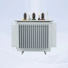
| Oil-immersed transformer | Oil-immersed self-cooled (ONAN) | Low cost, reliable insulation, most widely used | Most factory substations, distribution networks |
| Oil-immersed air-cooled (ONAF/OFAN) | Enhanced cooling for high-capacity transformers | Large power transmission transformers | |
| Oil-immersed water-cooled (OFWF) | High cooling efficiency for ultra-large capacity | Power plant main transformers | |
| Forced oil circulation cooling | Ultra-high cooling capacity for large transformers | UHV power transmission projects | |
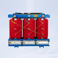
| Dry-type transformer | Cast resin / vacuum impregnated | No oil, fireproof, explosion-proof, environmentally friendly | Urban commercial buildings, indoor substations, mining |
| Gas-filled (SF6) transformer | SF6 gas insulation | Compact, maintenance-free, suitable for harsh environments | Urban compact substations, special industrial sites |
Classification by Winding Conductor Material
- Aluminum winding transformer: Low cost, light weight, traditional choice for factory substations
- Copper winding transformer: Lower loss, higher efficiency, longer service life, increasingly widely used in high-performance, energy-saving projects
Power Transformer Model Interpretation
The transformer model is a standardized code that fully reflects the product's parameters, structure, and performance. Understanding the model is the basis for correct selection and procurement.
Model Structure Diagram

Detailed Explanation of Each Code
1. Product Category Code
O: Autotransformer (general power transformers are not marked)
H: Electric arc furnace transformer
C: Induction furnace transformer
Z: Rectifier transformer
K: Mining transformer
Y: Test transformer
2. Phase Code
D: Single-phase transformer
S: Three-phase transformer (most common)
3. Cooling Method Code
F: Air-cooled
W: Water-cooled
Note: Oil-immersed self-cooled and air self-cooled are not marked
4. Oil Circulation Method Code
N: Natural circulation (not marked for common types)
O: Forced directed circulation
P: Forced circulation
5. Winding Number Code
S: Three-winding
Note: Double-winding is not marked (most common)
6. Conductor Material Code
L: Aluminum winding
Note: Copper winding is not marked
7. Voltage Regulation Method Code
Z: On-load voltage regulation
Note: No-load voltage regulation is not marked
8. Performance Level (Design Serial Number)
| Performance Level Code | Voltage Level (kV) | Performance Parameters - No-load Loss | Performance Parameters - Load Loss |
|---|---|---|---|
| 7 | 6, 10 | Complies with GB/T 6451 Group II | Complies with GB/T 6451 |
| ≥35 | Complies with GB/T 6451 | Complies with GB/T 6451 | |
| 8 | 6, 10 | Complies with GB/T 6451 Group I | Complies with GB/T 6451 |
| ≥35 | 10% lower than the average of GB/T 6451 Group I | Complies with GB/T 6451 | |
| 9 | 6, 10 | Distribution transformers comply with Grade A2 | 10% lower than the average of GB/T 6451 |
| ≥35 | 20% lower than the average of GB/T 6451 Group I | 10% lower than the average of GB/T 6451 | |
| 10 | 6, 10 | 20% lower than the average of GB/T 6451 Group I | 10% lower than the average of GB/T 6451 |
| ≥35 | 30% lower than the average of GB/T 6451 Group I | 10% lower than the average of GB/T 6451 | |
| 11 | 6, 10 | 30% lower than the average of GB/T 6451 Group I | 15% lower than the average of GB/T 6451 |
| ≥35 | 40% lower than the average of GB/T 6451 Group I | 15% lower than the average of GB/T 6451 |
9. Special Purpose/Structure Code
Z: Low noise
L: Cable outlet
X: On-site assembly type
J: Fully insulated neutral point
CY: Power plant auxiliary transformer
10. Rated Capacity & Rated Voltage
Rated capacity: Unit kVA, e.g., 20000, 360000
Rated voltage: Unit kV, e.g., 110, 220
✅️Model Interpretation Examples
Example 1: SFL7-20000/110
- S: Three-phase
- F: Air-cooled
- L: Aluminum winding
- 7: Performance level 7 (meets GB/T 6451 standard)
- 20000: Rated capacity 20000kVA
- 110: Rated voltage 110kVFull description: Three-phase, oil-immersed, air-cooled, double-winding, no-load voltage regulation, aluminum winding, 20000kVA, 110kV power transformer.
Example 2: SWPZ7-Z-360000/220
- S: Three-phase
- W: Water-cooled
- P: Forced oil circulation
- Z: On-load voltage regulation
- 7: Performance level 7
- Z: Low noise
- 360000: Rated capacity 360000kVA
- 220: Rated voltage 220kVFull description: Three-phase, oil-immersed, water-cooled, forced oil circulation, double-winding, on-load voltage regulation, copper winding, low noise, 360000kVA, 220kV power transformer.
GNEE ELECTRIC's Transformer Solutions
As a professional power transformer manufacturer, GNEE ELECTRIC provides customized solutions for global power projects, covering:
- Oil-immersed power transformers: 10kV-500kV voltage level, 100kVA-360000kVA capacity, energy-efficient copper winding series, meeting IEC, ANSI, and other international standards
- Dry-type distribution transformers: Cast resin type, fireproof and explosion-proof, suitable for indoor and special environments
- Special transformers: Autotransformers, rectifier transformers, mining transformers, etc., for industrial and mining, new energy, and other special scenarios
- Customized services: Tailor-made transformer models, voltage levels, and performance parameters according to customer project requirements, with complete after-sales support and technical guidance
Why Choose GNEE ELECTRIC?
✅ High Energy Efficiency: All products meet or exceed international energy efficiency standards, helping customers reduce operating costs
✅ Reliable Quality: Strictly follow IEC, GB, and other international standards, with full testing and certification
✅ Global Adaptability: Suitable for various power grid environments in Southeast Asia, the Middle East, Africa, Europe, and the Americas
✅ Customized Solutions: Professional technical team provides one-stop service from design to after-sales
Conclusion
Power transformers are the "heart" of the power system, and their correct selection and application are directly related to the safety, efficiency, and economy of power projects. Whether it is large-scale power transmission, industrial power distribution, or special scenario applications, GNEE ELECTRIC can provide you with high-quality, customized power transformer solutions.
If you have any questions about transformer selection, model customization, or technical parameters, please feel free to contact our professional sales team. We will provide you with the most suitable solution and competitive quotation.
Contact GNEE ELECTRIC today to power your project with reliable, efficient transformer solutions!
Send Inquiry