








How much voltage drop will a 1600kVA transformer produce at full load?
Jul 17, 2026
Leave a message
What Is the Full-Load Voltage Drop of a 1600 kVA Transformer?
- For a standard GB-compliant 1600 kVA distribution transformer, the full-load voltage regulation is typically 2%–4.5%.
- The most common industry value, based on a 0.8 power factor, is 3.5%–4.0%.
- On the 400 V low-voltage side, the corresponding voltage drop is typically 7–18 V.
In other words, when a 1600 kVA transformer operates at full load, the output voltage on the 400 V low-voltage side typically decreases from approximately 400 V at no load to around 382–393 V. This range is generally accepted as the industry standard.

Need lower voltage drop for your project?
GNEE Electric provides customized low‑impedance 1600 kVA transformers and free engineering consultation - click below to inquire.
Complimentary Engineering Consultation
What Is Full-Load Voltage Drop in a Transformer?
To understand full-load voltage drop, it is important to distinguish among the following three concepts:
No-Load Voltage - The output voltage at the transformer's secondary winding when no load is connected. Since no current flows through the winding, there is no voltage drop across the internal winding resistance or leakage reactance, and the output voltage is close to the rated value.

Full-Load Voltage - The output voltage at the secondary winding when the transformer is supplying its rated load. As load current flows through the winding resistance and leakage reactance, an internal voltage drop occurs, causing the secondary output voltage to decrease.

Voltage Regulation - This is the standard industry metric used to evaluate transformer voltage drop. It is defined as the difference between the no-load voltage and the load voltage of the same winding under specified load and power factor conditions, expressed as a percentage of the no-load voltage.
The calculation formula is:
- Voltage Regulation (%) = [(U₁ − U₂) / U₁] × 100%
Where:
- U₁ = No-load voltage
- U₂ = Load voltage
Important Note:
Percentage Impedance (Z%) and Voltage Regulation are two different parameters and should not be used interchangeably.
- Percentage Impedance (Z%) represents the percentage voltage required to circulate rated current when the secondary winding is short-circuited.
- Voltage Regulation, by contrast, quantifies the change in secondary voltage as the load varies from no load to full load while the primary voltage remains constant.
Using Z% directly to estimate voltage regulation without separating its resistive (R%) and reactive (X%) components will result in inaccurate calculations.
Three Key Factors That Determine the Full-Load Voltage Drop of a 1600 kVA Transformer
1. Transformer Percentage Impedance (The Most Important Factor)
The transformer's percentage impedance (impedance voltage) is the primary factor that determines the magnitude of the full-load voltage drop. In general, the higher the percentage impedance, the greater the internal voltage drop under full-load conditions.
According to GB/T 6451, the standard percentage impedance for 630 kVA to 1600 kVA oil-immersed distribution transformers is 4.5%. For 1600 kVA dry-type transformers, the typical percentage impedance is 6%. Overall, the percentage impedance of a 1600 kVA distribution transformer generally falls within the range of 4.0% to 6.5%.
This is the primary reason why dry-type transformers typically experience a greater full-load voltage drop than oil-immersed transformers-their percentage impedance is higher.
【Pro Tip: Lower impedance is not always better. While it reduces voltage drop, it also increases short-circuit current. At GNEE Electric, we help you find the sweet spot - low enough for stable voltage, but high enough to keep your switchgear safe.】
2. Load Power Factor (Often Overlooked in Industrial Applications)
The load power factor has a significant impact on voltage regulation. As the power factor decreases, voltage regulation increases, resulting in a larger voltage drop under load.
Industrial systems often contain a high proportion of inductive loads, such as electric motors, which reduce the operating power factor and increase the voltage drop. When the power factor falls below 0.5, the voltage drop becomes considerably more pronounced.
Voltage regulation reaches its minimum value at a unity power factor (1.0). As the power factor decreases under lagging power factor conditions, voltage regulation increases accordingly.
【Pro Tip: Many customers blame the transformer when they see voltage drop, but in 80% of cases, the real culprit is a low power factor. Before replacing your transformer, have GNEE Electric evaluate your reactive power compensation system - a simple capacitor bank upgrade often fixes the issue at a fraction of the cost.】
3. Transformer Type: Dry-Type vs. Oil-Immersed
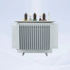
- Oil-immersed transformers typically have a lower percentage impedance (approximately 4.5%), resulting in a relatively smaller full-load voltage drop.
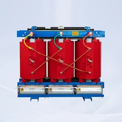
- Dry-type transformers generally have a higher percentage impedance (approximately 6%), leading to a relatively larger full-load voltage drop.
Industry Standard Performance Data for 1600 kVA Transformer Types
| Transformer Type | Percentage Impedance | Voltage Regulation (Full-Load Voltage Drop) | Actual Voltage Drop on 400 V LV Side |
|---|---|---|---|
| 1600 kVA Oil-Immersed Transformer | 4.5% | 2.5%–3.5% | 10–14 V |
| 1600 kVA Dry-Type Transformer | 6.0% | 3.5%–4.5% | 14–18 V |
- For 1600 kVA oil-immersed distribution transformers, the standard percentage impedance specified by GB/T 6451 is 4.5%.
- For 1600 kVA dry-type transformers, the percentage impedance is typically 6%, in accordance with GB/T 10228 and related technical standards.
How to Calculate the Full-Load Voltage Drop of a 1600 kVA Transformer
The transformer voltage-drop calculation formula is:
- ΔU% = β × (U_R% × cosφ + U_X% × sinφ)
Where:
- β = Transformer load factor (actual load ÷ rated capacity)
- U_R% = Resistive component of the percentage impedance
- U_X% = Reactive component of the percentage impedance
- cosφ = Load power factor
Calculation Example
Transformer specifications:
- Rated voltage: 10/0.4 kV
- Rated capacity: 1600 kVA
- No-load loss: 1.95 kW
- Load loss (short-circuit loss): 11.73 kW
- Load factor: β = 0.625
- Power factor: cosφ = 0.8
Under full-load conditions (β = 1), the transformer reaches its maximum voltage drop. As the load factor decreases, the load current decreases accordingly, and the voltage drop is reduced proportionally.
【Pro Tip: If you are not an engineer, you don't need to do this math manually. GNEE Electric provides a free voltage-drop calculation report with every inquiry. We run the numbers for your specific load and cable length, so you get precise answers without the headache.】
Complimentary Calculation Report
Why Is the Actual Voltage Drop of My 1600 kVA Transformer Much Higher Than the Calculated Value?
If the measured voltage drop of your 1600 kVA transformer is significantly greater than the theoretical value, one or more of the following factors may be responsible:
1. Excessive Loading or Continuous Overloading
Operating a transformer above its rated capacity substantially increases the voltage drop. In one documented case, a 1600 kVA transformer operated under continuous overload, with the load current reaching 2,500–2,690 A. As a result, the voltage at the transformer terminals dropped to only 379 V.
It is important to note that a 1600 kVA rated capacity does not mean the transformer can continuously supply the full inrush or starting demand of large loads.
2. Excessive Feeder Length
Long feeder cables can produce significant additional voltage drop beyond the transformer itself.
In one project, a 1600 kVA transformer supplied a 160 kW motor through approximately 220 m of 240 mm² aluminum cable. During motor starting, the terminal voltage dropped to only 260 V. The excessive feeder voltage drop resulted in insufficient motor terminal voltage and inadequate starting torque.
Even after installing a second 240 mm² aluminum cable in parallel, the voltage remained as low as 300 V when the current reached 1,100 A.
3. Low Power Factor
A low load power factor increases transformer voltage regulation, resulting in a larger voltage drop.
For example, in one industrial installation, the transformer output voltage measured 379 V with a power factor of 0.90. After passing through 100 m of power cable, the voltage at the load had fallen further to 345 V.
4. Undersized Power Cables
Selecting an inadequate cable cross-sectional area can significantly increase voltage drop.
In some installations, the total feeder voltage drop may reach approximately 8%, well above the commonly accepted design limit of 5%.
5. Insufficient Actual Transformer Capacity or Manufacturing Defects
If all other factors have been ruled out, the transformer itself should be evaluated. Some field engineers have questioned whether an installed transformer was constructed with insufficient active materials or did not actually provide its rated 1600 kVA capacity, resulting in excessive voltage drop under load.
How to Reduce the Full-Load Voltage Drop of a 1600 kVA Transformer?
Select a Transformer with Lower Percentage Impedance
The percentage impedance of transformers rated 1600 kVA and below is not always fixed. For applications with strict voltage regulation requirements, a transformer with a customized lower percentage impedance can be specified.
Maintain a Reasonable Load Factor
To minimize voltage drop and improve operating reliability, it is recommended to keep the transformer load factor below 80% whenever possible. Avoid prolonged operation at full load or under overload conditions.
Install Reactive Power Compensation
Improving the power factor through reactive power compensation can significantly reduce voltage drop. Local compensation decreases the reactive current flowing through the transformer, thereby reducing both voltage drop and power losses.
【Pro Tip: When adding capacitors, avoid over-compensation. An leading power factor can actually raise the voltage above acceptable levels. GNEE Electric can help you size the capacitor bank correctly to hit the optimal 0.92–0.95 range.】
Use High-Quality Core and Winding Materials
Transformers manufactured with low-loss magnetic cores and high-quality windings have lower internal impedance, helping to reduce voltage drop during operation.
Use an On-Load Tap Changer (OLTC)
An On-Load Tap Changer (OLTC) allows the transformer tap position to be adjusted while the transformer remains energized and carrying load. By changing the transformer turns ratio, the output voltage can be regulated to compensate for voltage variations and maintain the desired voltage level.
Select the Appropriate Cable Size
Power cables should be sized not only according to their current-carrying capacity (ampacity) but also based on allowable voltage drop. Proper cable sizing is essential for maintaining acceptable voltage at the load.
Minimize the Feeder Length
Whenever practical, install the transformer as close as possible to the load center. Shorter feeder lengths reduce line voltage drop and improve overall system voltage performance.
Adjust the High-Voltage Tap Position
Distribution transformers are typically equipped with high-voltage tap changers. Adjusting the tap position can increase or decrease the secondary output voltage to compensate for supply voltage variations and operating conditions.
Why Choose GNEE Electric?
As a professional power transformer manufacturer, GNEE Electric provides customized low-impedance 1600 kVA transformer solutions to help customers minimize voltage drop and improve overall power system performance.
✅ Manufactured in strict accordance with IEC 60076 and GB 1094 standards
✅ Custom low-impedance designs available - percentage impedance can be customized to as low as 4.0% for oil-immersed transformers, while dry-type transformers can be optimized to below 5.0%, subject to application requirements and system short-circuit considerations.
✅ Factory test reports included - each transformer is supplied with measured voltage regulation and routine test reports, ensuring complete traceability of performance data.

✅ Free transformer selection service - our engineers recommend the most suitable transformer configuration based on your load profile, installation conditions, and operating requirements.
✅ Free voltage-drop calculation service - we evaluate transformer voltage drop, feeder voltage drop, motor starting voltage drop, and other critical system parameters to support reliable system design.
Whether you require an oil-immersed or dry-type 1600 kVA transformer, or have specific voltage regulation and voltage-drop requirements, GNEE Electric can provide a solution tailored to your application.
Contact GNEE Electric today to receive your customized 1600 kVA transformer selection proposal and a professional voltage-drop calculation report.


Send Inquiry